
 USD
USDMi Idioma


Mi Divisa
Ayuda
Cómo hacer un pedidoProblemas al hacer un pedidoPreguntas más frecuentesContáctenosContact Us (Suppliers)Acerca de JunoJuno DailyEstrenos de esta semanaDJ & Studio StoreTagsComentariosPolítica de privacidadReturns & refundsCondiciones de usoFinanceJuno Vinyl DistributionJuno Vinyl WholesaleJuno Marketing and PR departmentPromote your label / releases


Receive new release alerts for Doepfer
Filter

Equipment
Format
Featured
Price
Tags

Otros clientes también compraron...
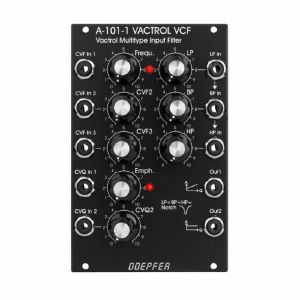
Doepfer A-101-1 Vactrol VCF Vactrol Multi-Type Input Filter Module (silver) (filter synth module)
Cat: 682307 Rel: 06 Apr 18
Vactrol-based multimode filter based on a schematic by Nyle Steiner, featuring separate inputs for lowpass, bandpass & highpass
Notes: This filter's unique feature is that different filter types are realized by injecting the audio signal at different points of the circuit. For this reason, the A-101-1 has three inputs with level control: one lowpass input which is normalized to the bandpass input, which itself is normalized to the highpass input. The level controls make it possible to mix the filters and to generate new filter types. e.g. with all three filter levels turned to maximum level you get a notch filter.
Furthermore, the cutoff frequency influences which filter type is "monitored". This way you can blend from LP over BP to HP with increasing cutoff, known as "frequency scanning". Interesting effects happen when three different audio signals are used because they are both morphed and filtered at the same time.
… Read moreFurthermore, the cutoff frequency influences which filter type is "monitored". This way you can blend from LP over BP to HP with increasing cutoff, known as "frequency scanning". Interesting effects happen when three different audio signals are used because they are both morphed and filtered at the same time.
out of stock $129.55
Otros clientes también compraron...
Doepfer A-101-1v Vactrol Multi-Type Input Filter Vintage Edition Module (black) (filter synth module)
Cat: 682313 Rel: 26 Mar 18
Vactrol-based multimode filter based on a schematic by Nyle Steiner, featuring separate inputs for lowpass, bandpass & highpass
Notes: This filter's unique feature is that different filter types are realized by injecting the audio signal at different points of the circuit. For this reason, the A-101-1 has three inputs with level control: one lowpass input which is normalized to the bandpass input, which itself is normalized to the highpass input. The level controls make it possible to mix the filters and to generate new filter types. e.g. with all three filter levels turned to maximum level you get a notch filter.
Furthermore, the cutoff frequency influences which filter type is "monitored". This way you can blend from LP over BP to HP with increasing cutoff, known as "frequency scanning". Interesting effects happen when three different audio signals are used because they are both morphed and filtered at the same time.
Vintage edition with black faceplate and custom knobs.
… Read moreFurthermore, the cutoff frequency influences which filter type is "monitored". This way you can blend from LP over BP to HP with increasing cutoff, known as "frequency scanning". Interesting effects happen when three different audio signals are used because they are both morphed and filtered at the same time.
Vintage edition with black faceplate and custom knobs.
out of stock $146.02
Otros clientes también compraron...
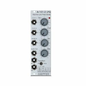
Doepfer A-101-2 LPG Vactrol Low Pass Gate Module (silver) (low pass gate synth module)
Cat: 682314 Rel: 26 Mar 18
Vactrol based combination of resonant 12dB lowpass filter and/or VCA - inspired by the Buchla 292
Notes: A Low Pass Gate (LPG) can be a low pass filter, a VCA or a combination of both. This means both the harmonic content and volume can be controlled simultaneously which resembles the behaviour of many instruments: the louder, the more harmonics.
The A-101-2's mode of operation is set with a switch: left position is low pass, right is VCA and the combo mode is in the centre. Alternatively, you can activate the modes with gate signals which is the reason for two gate inputs; this is very interesting in combination with clock dividers or trigger sequencers.
- Gate 1 high & gate 2 low = low pass mode
- Gate 1 low & gate 2 high = VCA mode
- Both Gate 1 & 2 high = combo mode
The A-101-2 has an aggressive sound, compared to other LPGs and its resonance goes up to self-oscillation which not many LPGs offer. The oscillation is rather dirty and far from being a sine wave.
3U Eurorack module, 8HP wide, 50mm deep.
… Read moreThe A-101-2's mode of operation is set with a switch: left position is low pass, right is VCA and the combo mode is in the centre. Alternatively, you can activate the modes with gate signals which is the reason for two gate inputs; this is very interesting in combination with clock dividers or trigger sequencers.
- Gate 1 high & gate 2 low = low pass mode
- Gate 1 low & gate 2 high = VCA mode
- Both Gate 1 & 2 high = combo mode
The A-101-2 has an aggressive sound, compared to other LPGs and its resonance goes up to self-oscillation which not many LPGs offer. The oscillation is rather dirty and far from being a sine wave.
3U Eurorack module, 8HP wide, 50mm deep.
1 in stock $104.29
Click for better price!
or call +44 20 7424 1960
quote 682314
quote 682314
Otros clientes también compraron...
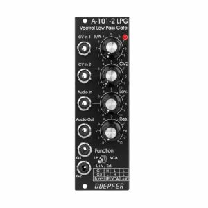
Cat: 682317 Rel: 26 Mar 18
Vactrol based combination of resonant 12dB lowpass filter and/or VCA - inspired by the Buchla 292
Notes: A Low Pass Gate (LPG) can be a low pass filter, a VCA or a combination of both. This means both the harmonic content and volume can be controlled simultaneously which resembles the behaviour of many instruments: the louder, the more harmonics.
The A-101-2's mode of operation is set with a switch: left position is low pass, right is VCA and the combo mode is in the centre. Alternatively, you can activate the modes with gate signals which is the reason for two gate inputs; this is very interesting in combination with clock dividers or trigger sequencers.
- Gate 1 high & gate 2 low = low pass mode
- Gate 1 low & gate 2 high = VCA mode
- Both Gate 1 & 2 high = combo mode
The A-101-2 has an aggressive sound, compared to other LPGs and its resonance goes up to self-oscillation which not many LPGs offer. The oscillation is rather dirty and far from being a sine wave.
Vintage edition with black faceplate and custom knobs.
3U Eurorack module, 8HP wide, 50mm deep.
… Read moreThe A-101-2's mode of operation is set with a switch: left position is low pass, right is VCA and the combo mode is in the centre. Alternatively, you can activate the modes with gate signals which is the reason for two gate inputs; this is very interesting in combination with clock dividers or trigger sequencers.
- Gate 1 high & gate 2 low = low pass mode
- Gate 1 low & gate 2 high = VCA mode
- Both Gate 1 & 2 high = combo mode
The A-101-2 has an aggressive sound, compared to other LPGs and its resonance goes up to self-oscillation which not many LPGs offer. The oscillation is rather dirty and far from being a sine wave.
Vintage edition with black faceplate and custom knobs.
3U Eurorack module, 8HP wide, 50mm deep.
out of stock $103.20
Otros clientes también compraron...
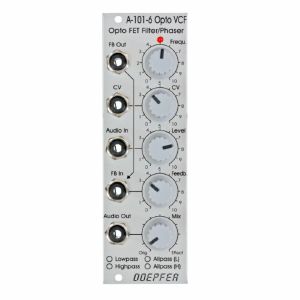
Doepfer A-101-6 6-Stage VC Opto-FET Filter & Phaser Module (silver) (filter/phase shifter/effect synth module)
Cat: 682323 Rel: 26 Mar 18
6-stage VC Opto-FET filter/phaser - 8HP
Notes: A-101-6 is a new filter module that uses so-called opto FET's to control the filter frequency. Opto FET's are very similar to Vactrols, but use light dependent field effect transistors (FET's) instead of light dependent resistors (LDR's). An opto FET is a combination of a light-dependent FET and an LED, both put into a small light-proof case. The advantage, compared to vactrols, is a much faster response of opto FET's compared to LDR's - this allows much faster attack/decay times and even FM effects.
The variable resistors corresponds to the opto FET. The brightness of the Opto FET LED's, and consequently the filter frequency, can be adjusted manually (Frequ. control) and controlled by means of an external control voltage (CV) with attenuator. The LED at the front panel reflects the LED brightness inside the opto FET's.
The type of filter is chosen by jumpers on the PC board (factory setting: low pass). The type of filter determined by the jumpers positions can be marked by means of a water-resistant felt pen at the front panel.
The resonance is controlled by the Feedback control up to self-oscillation. By means of a trimming potentiometer the maximal feedback can be adjusted. High feedback values can be used mainly in the all-pass mode to obtain very extreme self-oscillation sounds. Even an external feedback signal can be used instead of the internal feedback connection (FB In socket). Whenever the filter type is changed by means of the jumpers the trimming potentiometer for the maximal feedback has to be re-adjusted.
The Mix control is used to pan between the original signal (CCW position) and the effect signal (CW position). In filter mode (LP/HP) this control is usually set fully CW. In the all-pass modes one obtains phasing sounds at centre position or "pure" all-pass sound in fully CW position.
… Read moreThe variable resistors corresponds to the opto FET. The brightness of the Opto FET LED's, and consequently the filter frequency, can be adjusted manually (Frequ. control) and controlled by means of an external control voltage (CV) with attenuator. The LED at the front panel reflects the LED brightness inside the opto FET's.
The type of filter is chosen by jumpers on the PC board (factory setting: low pass). The type of filter determined by the jumpers positions can be marked by means of a water-resistant felt pen at the front panel.
The resonance is controlled by the Feedback control up to self-oscillation. By means of a trimming potentiometer the maximal feedback can be adjusted. High feedback values can be used mainly in the all-pass mode to obtain very extreme self-oscillation sounds. Even an external feedback signal can be used instead of the internal feedback connection (FB In socket). Whenever the filter type is changed by means of the jumpers the trimming potentiometer for the maximal feedback has to be re-adjusted.
The Mix control is used to pan between the original signal (CCW position) and the effect signal (CW position). In filter mode (LP/HP) this control is usually set fully CW. In the all-pass modes one obtains phasing sounds at centre position or "pure" all-pass sound in fully CW position.
1 in stock $106.49
Click for better price!
or call +44 20 7424 1960
quote 682323
quote 682323
Otros clientes también compraron...
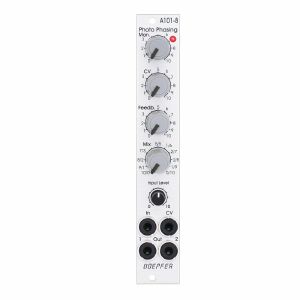
Doepfer A-101-8 Photo Phasing 8-Stage Phase Shifter Module (silver) (phase shifter/effect synth module)
Cat: 945411 Rel: 13 Jun 23
An eight stage phase shifter module in 4HP.
Notes: Module A-101-8 is a 8-stage phase shifter which uses light-sensitive resistors (LDR) and is a replica of the Compact Phasing A manufactured by the company Schulte in the seventies. The actual phasing circuit is identical to the historic model. Only the illumination control of the LDRs is different: the A-101-8 uses LEDs to illuminate the LDRs, the historic model used incandescent miniature lamps. And the A-101-8 has no built-in LFO but can be controlled by any external control voltage source (e.g. LFO, ADSR, random, Theremin, ribbon controller, sequencer, midi). The phasing offset (i.e. the base value for the phase shifting) and the modulation depth of the external control signal can be adjusted separately. The Compact Phasing A had no offset control but only a depth control for the built-in LFO. Feedback and mixing ratio of the output signal are set by two controls. The audio input is equipped with an attenuator. The module has two audio outputs available (same as the historic model) and a visual display of the phase shifting.
The module has these controls and in/outputs available:
Control Man. : manual control of the phase shift offset (base value)
Control CV: attenuator for the signal applied to the CV socket
Control Feedb.: Feedback or Resonance (similar function as filter resonance/feedback/emphasis)
Control Mix: sets the mixing ratio between original and phase shift signal appearing at output 1
fully CCW: only the modified input signal appears at output 1 (see note below *)
center: a mixture between the modified input signal and the phase shift signal appears at output 1, that's the standard position for the classical phasing effect
fully CW: the pure phase shifted signal appears at output 1 (e.g. for vibrato effects)
Control Input Level: attenuator for signal applied to the In socket
Socket In: audio input
Socket CV: control voltage input
Socket Out 1: audio output 1 (mix signal)
Socket Out 2: audio output 2 (modified input signal)
LED: visual control of the phase shift
The module has some peculiarities (same as the historic model):
The input signal is processed at first by a pre-stage which outputs a "modified" input signal (*). This signal is not processed by the phase shift stages but is affected by the feedback setting. Only when feedback is set to zero this signal is identical to the input signal. Otherwise it contains feedback components.
This signal is output on socket Out 2.
When both output sockets Out 1 and Out 2 are used as stereo channels one obtains a spatial stereo sound effect.
The same signals is also used for the CCW position of the mix control. With mix control fully CCW the unmodified signal appears only if the feedback control is set to zero. Otherwise it contains feedback components.
The historic model had two audio inputs: one 5-pin DIN socket and a 1/4" jack socket. The DIN socket was intended for high-level line signals. When the 1/4" jack socket was used the amplification of the pre-stage increased by about 100. The 1/4" jack socket was intended for low level signals (e.g. electric guitars or microphones). For this feature the A-101-8 has an internal jumper that can be used to increase the amplification. As long as the module is used within the A-100 system usually the lower amplification is used to avoid distortion.
The 8 photo resistors and LEDs are assembled within an small lighproof box. In addition the pc boards are made of lighproof black material to avoid interfering light from other modules or the bus board.
Dimensions
4 HP
45 mm deep
Current Draw
30 mA +12V
30 mA -12V
… Read moreThe module has these controls and in/outputs available:
Control Man. : manual control of the phase shift offset (base value)
Control CV: attenuator for the signal applied to the CV socket
Control Feedb.: Feedback or Resonance (similar function as filter resonance/feedback/emphasis)
Control Mix: sets the mixing ratio between original and phase shift signal appearing at output 1
fully CCW: only the modified input signal appears at output 1 (see note below *)
center: a mixture between the modified input signal and the phase shift signal appears at output 1, that's the standard position for the classical phasing effect
fully CW: the pure phase shifted signal appears at output 1 (e.g. for vibrato effects)
Control Input Level: attenuator for signal applied to the In socket
Socket In: audio input
Socket CV: control voltage input
Socket Out 1: audio output 1 (mix signal)
Socket Out 2: audio output 2 (modified input signal)
LED: visual control of the phase shift
The module has some peculiarities (same as the historic model):
The input signal is processed at first by a pre-stage which outputs a "modified" input signal (*). This signal is not processed by the phase shift stages but is affected by the feedback setting. Only when feedback is set to zero this signal is identical to the input signal. Otherwise it contains feedback components.
This signal is output on socket Out 2.
When both output sockets Out 1 and Out 2 are used as stereo channels one obtains a spatial stereo sound effect.
The same signals is also used for the CCW position of the mix control. With mix control fully CCW the unmodified signal appears only if the feedback control is set to zero. Otherwise it contains feedback components.
The historic model had two audio inputs: one 5-pin DIN socket and a 1/4" jack socket. The DIN socket was intended for high-level line signals. When the 1/4" jack socket was used the amplification of the pre-stage increased by about 100. The 1/4" jack socket was intended for low level signals (e.g. electric guitars or microphones). For this feature the A-101-8 has an internal jumper that can be used to increase the amplification. As long as the module is used within the A-100 system usually the lower amplification is used to avoid distortion.
The 8 photo resistors and LEDs are assembled within an small lighproof box. In addition the pc boards are made of lighproof black material to avoid interfering light from other modules or the bus board.
Dimensions
4 HP
45 mm deep
Current Draw
30 mA +12V
30 mA -12V
4 in stock $108.69
Otros clientes también compraron...
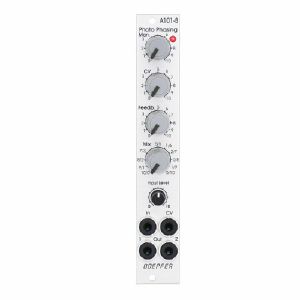
Doepfer A-101-8 Photo Phasing 8-Stage Phase Shifter Module (silver) (B-STOCK) (phase shifter/effect synth module)
Cat: 966281 Rel: 01 Jan 90
B-STOCK: Box opened, but product is in excellent condition and in perfect working order
Notes: ***B-STOCK: Box opened, but product is in excellent condition and in perfect working order***
Module A-101-8 is a 8-stage phase shifter which uses light-sensitive resistors (LDR) and is a replica of the Compact Phasing A manufactured by the company Schulte in the seventies. The actual phasing circuit is identical to the historic model. Only the illumination control of the LDRs is different: the A-101-8 uses LEDs to illuminate the LDRs, the historic model used incandescent miniature lamps. And the A-101-8 has no built-in LFO but can be controlled by any external control voltage source (e.g. LFO, ADSR, random, Theremin, ribbon controller, sequencer, midi). The phasing offset (i.e. the base value for the phase shifting) and the modulation depth of the external control signal can be adjusted separately. The Compact Phasing A had no offset control but only a depth control for the built-in LFO. Feedback and mixing ratio of the output signal are set by two controls. The audio input is equipped with an attenuator. The module has two audio outputs available (same as the historic model) and a visual display of the phase shifting.
The module has these controls and in/outputs available:
Control Man. : manual control of the phase shift offset (base value)
Control CV: attenuator for the signal applied to the CV socket
Control Feedb.: Feedback or Resonance (similar function as filter resonance/feedback/emphasis)
Control Mix: sets the mixing ratio between original and phase shift signal appearing at output 1
fully CCW: only the modified input signal appears at output 1 (see note below *)
center: a mixture between the modified input signal and the phase shift signal appears at output 1, that's the standard position for the classical phasing effect
fully CW: the pure phase shifted signal appears at output 1 (e.g. for vibrato effects)
Control Input Level: attenuator for signal applied to the In socket
Socket In: audio input
Socket CV: control voltage input
Socket Out 1: audio output 1 (mix signal)
Socket Out 2: audio output 2 (modified input signal)
LED: visual control of the phase shift
The module has some peculiarities (same as the historic model):
The input signal is processed at first by a pre-stage which outputs a "modified" input signal (*). This signal is not processed by the phase shift stages but is affected by the feedback setting. Only when feedback is set to zero this signal is identical to the input signal. Otherwise it contains feedback components.
This signal is output on socket Out 2.
When both output sockets Out 1 and Out 2 are used as stereo channels one obtains a spatial stereo sound effect.
The same signals is also used for the CCW position of the mix control. With mix control fully CCW the unmodified signal appears only if the feedback control is set to zero. Otherwise it contains feedback components.
The historic model had two audio inputs: one 5-pin DIN socket and a 1/4" jack socket. The DIN socket was intended for high-level line signals. When the 1/4" jack socket was used the amplification of the pre-stage increased by about 100. The 1/4" jack socket was intended for low level signals (e.g. electric guitars or microphones). For this feature the A-101-8 has an internal jumper that can be used to increase the amplification. As long as the module is used within the A-100 system usually the lower amplification is used to avoid distortion.
The 8 photo resistors and LEDs are assembled within an small lighproof box. In addition the pc boards are made of lighproof black material to avoid interfering light from other modules or the bus board.
Dimensions
4 HP
45 mm deep
Current Draw
30 mA +12V
30 mA -12V
… Read moreModule A-101-8 is a 8-stage phase shifter which uses light-sensitive resistors (LDR) and is a replica of the Compact Phasing A manufactured by the company Schulte in the seventies. The actual phasing circuit is identical to the historic model. Only the illumination control of the LDRs is different: the A-101-8 uses LEDs to illuminate the LDRs, the historic model used incandescent miniature lamps. And the A-101-8 has no built-in LFO but can be controlled by any external control voltage source (e.g. LFO, ADSR, random, Theremin, ribbon controller, sequencer, midi). The phasing offset (i.e. the base value for the phase shifting) and the modulation depth of the external control signal can be adjusted separately. The Compact Phasing A had no offset control but only a depth control for the built-in LFO. Feedback and mixing ratio of the output signal are set by two controls. The audio input is equipped with an attenuator. The module has two audio outputs available (same as the historic model) and a visual display of the phase shifting.
The module has these controls and in/outputs available:
Control Man. : manual control of the phase shift offset (base value)
Control CV: attenuator for the signal applied to the CV socket
Control Feedb.: Feedback or Resonance (similar function as filter resonance/feedback/emphasis)
Control Mix: sets the mixing ratio between original and phase shift signal appearing at output 1
fully CCW: only the modified input signal appears at output 1 (see note below *)
center: a mixture between the modified input signal and the phase shift signal appears at output 1, that's the standard position for the classical phasing effect
fully CW: the pure phase shifted signal appears at output 1 (e.g. for vibrato effects)
Control Input Level: attenuator for signal applied to the In socket
Socket In: audio input
Socket CV: control voltage input
Socket Out 1: audio output 1 (mix signal)
Socket Out 2: audio output 2 (modified input signal)
LED: visual control of the phase shift
The module has some peculiarities (same as the historic model):
The input signal is processed at first by a pre-stage which outputs a "modified" input signal (*). This signal is not processed by the phase shift stages but is affected by the feedback setting. Only when feedback is set to zero this signal is identical to the input signal. Otherwise it contains feedback components.
This signal is output on socket Out 2.
When both output sockets Out 1 and Out 2 are used as stereo channels one obtains a spatial stereo sound effect.
The same signals is also used for the CCW position of the mix control. With mix control fully CCW the unmodified signal appears only if the feedback control is set to zero. Otherwise it contains feedback components.
The historic model had two audio inputs: one 5-pin DIN socket and a 1/4" jack socket. The DIN socket was intended for high-level line signals. When the 1/4" jack socket was used the amplification of the pre-stage increased by about 100. The 1/4" jack socket was intended for low level signals (e.g. electric guitars or microphones). For this feature the A-101-8 has an internal jumper that can be used to increase the amplification. As long as the module is used within the A-100 system usually the lower amplification is used to avoid distortion.
The 8 photo resistors and LEDs are assembled within an small lighproof box. In addition the pc boards are made of lighproof black material to avoid interfering light from other modules or the bus board.
Dimensions
4 HP
45 mm deep
Current Draw
30 mA +12V
30 mA -12V
out of stock $119.04
Otros clientes también compraron...
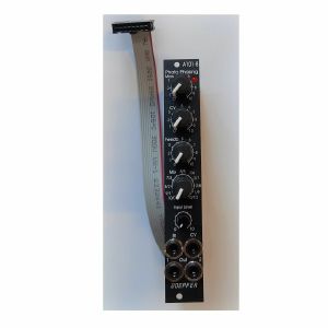
Doepfer A-101-8v Photo Phasing 8-Stage Phase Shifter Vintage Edition Module (black) (phase shifter/effect synth module)
Cat: 950741 Rel: 19 Jun 23
8-stage phase shifter module - 4HP.
Notes: Module A-101-8V is a 8-stage phase shifter which uses light-sensitive resistors (LDR) and is a replica of the Compact Phasing A manufactured by the company Schulte in the seventies. The actual phasing circuit is identical to the historic model. Only the illumination control of the LDRs is different: the A-101-8 uses LEDs to illuminate the LDRs, the historic model used incandescent miniature lamps. And the A-101-8 has no built-in LFO but can be controlled by any external control voltage source (e.g. LFO, ADSR, random, Theremin, ribbon controller, sequencer, midi). The phasing offset (i.e. the base value for the phase shifting) and the modulation depth of the external control signal can be adjusted separately. The Compact Phasing A had no offset control but only a depth control for the built-in LFO. Feedback and mixing ratio of the output signal are set by two controls. The audio input is equipped with an attenuator. The module has two audio outputs available (same as the historic model) and a visual display of the phase shifting.
The module has these controls and in/outputs available:
Control Man. : manual control of the phase shift offset (base value)
Control CV: attenuator for the signal applied to the CV socket
Control Feedb.: Feedback or Resonance (similar function as filter resonance/feedback/emphasis)
Control Mix: sets the mixing ratio between original and phase shift signal appearing at output 1
fully CCW: only the modified input signal appears at output 1 (see note below *)
center: a mixture between the modified input signal and the phase shift signal appears at output 1, that's the standard position for the classical phasing effect
fully CW: the pure phase shifted signal appears at output 1 (e.g. for vibrato effects)
Control Input Level: attenuator for signal applied to the In socket
Socket In: audio input
Socket CV: control voltage input
Socket Out 1: audio output 1 (mix signal)
Socket Out 2: audio output 2 (modified input signal)
LED: visual control of the phase shift
The module has some peculiarities (same as the historic model):
The input signal is processed at first by a pre-stage which outputs a "modified" input signal (*). This signal is not processed by the phase shift stages but is affected by the feedback setting. Only when feedback is set to zero this signal is identical to the input signal. Otherwise it contains feedback components.
This signal is output on socket Out 2.
When both output sockets Out 1 and Out 2 are used as stereo channels one obtains a spatial stereo sound effect.
The same signals is also used for the CCW position of the mix control. With mix control fully CCW the unmodified signal appears only if the feedback control is set to zero. Otherwise it contains feedback components.
The historic model had two audio inputs: one 5-pin DIN socket and a 1/4" jack socket. The DIN socket was intended for high-level line signals. When the 1/4" jack socket was used the amplification of the pre-stage increased by about 100. The 1/4" jack socket was intended for low level signals (e.g. electric guitars or microphones). For this feature the A-101-8 has an internal jumper that can be used to increase the amplification. As long as the module is used within the A-100 system usually the lower amplification is used to avoid distortion.
The 8 photo resistors and LEDs are assembled within an small lightproof box. In addition the pc boards are made of lightproof black material to avoid interfering light from other modules or the bus board.
Power consumption: 30mA at +12 V and 30mA at -12 V
Depth: 45mm
HP : 4
… Read moreThe module has these controls and in/outputs available:
Control Man. : manual control of the phase shift offset (base value)
Control CV: attenuator for the signal applied to the CV socket
Control Feedb.: Feedback or Resonance (similar function as filter resonance/feedback/emphasis)
Control Mix: sets the mixing ratio between original and phase shift signal appearing at output 1
fully CCW: only the modified input signal appears at output 1 (see note below *)
center: a mixture between the modified input signal and the phase shift signal appears at output 1, that's the standard position for the classical phasing effect
fully CW: the pure phase shifted signal appears at output 1 (e.g. for vibrato effects)
Control Input Level: attenuator for signal applied to the In socket
Socket In: audio input
Socket CV: control voltage input
Socket Out 1: audio output 1 (mix signal)
Socket Out 2: audio output 2 (modified input signal)
LED: visual control of the phase shift
The module has some peculiarities (same as the historic model):
The input signal is processed at first by a pre-stage which outputs a "modified" input signal (*). This signal is not processed by the phase shift stages but is affected by the feedback setting. Only when feedback is set to zero this signal is identical to the input signal. Otherwise it contains feedback components.
This signal is output on socket Out 2.
When both output sockets Out 1 and Out 2 are used as stereo channels one obtains a spatial stereo sound effect.
The same signals is also used for the CCW position of the mix control. With mix control fully CCW the unmodified signal appears only if the feedback control is set to zero. Otherwise it contains feedback components.
The historic model had two audio inputs: one 5-pin DIN socket and a 1/4" jack socket. The DIN socket was intended for high-level line signals. When the 1/4" jack socket was used the amplification of the pre-stage increased by about 100. The 1/4" jack socket was intended for low level signals (e.g. electric guitars or microphones). For this feature the A-101-8 has an internal jumper that can be used to increase the amplification. As long as the module is used within the A-100 system usually the lower amplification is used to avoid distortion.
The 8 photo resistors and LEDs are assembled within an small lightproof box. In addition the pc boards are made of lightproof black material to avoid interfering light from other modules or the bus board.
Power consumption: 30mA at +12 V and 30mA at -12 V
Depth: 45mm
HP : 4
out of stock $144.91
Otros clientes también compraron...
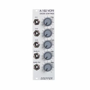
Doepfer A-102 VCF9 Diode Low Pass Filter Module (filter synth module)
Cat: 692503 Rel: 18 Jun 18
Reproduction of the legendary British diode lowpass filter - 8HP
Notes: Module A-102 is a reproduction of the legendary low pass filter design that uses diodes in the filter stage as frequency controlling elements - resulting in "strange" resonance behaviour and frequency response, as resonance and frequency are not independent from another.
As for the rest, the A-102 is identical to the A-120 Moog low pass filter, the A-103 (18dB TB303 Filter) i.e. the same controls, inputs and outputs. Only the filter sound is different:
- Manual control of filter frequency
- 3 CV inputs (CV1, CV2, CV3), 2 of them with attenuator (CV2, CV3)
- Input level control
- Resonance control up to self-oscillation (depends upon the frequency setting for the A-102)
… Read moreAs for the rest, the A-102 is identical to the A-120 Moog low pass filter, the A-103 (18dB TB303 Filter) i.e. the same controls, inputs and outputs. Only the filter sound is different:
- Manual control of filter frequency
- 3 CV inputs (CV1, CV2, CV3), 2 of them with attenuator (CV2, CV3)
- Input level control
- Resonance control up to self-oscillation (depends upon the frequency setting for the A-102)
out of stock $84.53
Otros clientes también compraron...
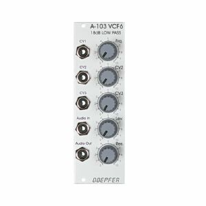
Doepfer A-103 VCF6 18dB Low Pass Filter Module (filter synth module)
Cat: 692504 Rel: 18 Jun 18
18dB low pass filter based on a modified Moog cascade - 8HP
Notes: Module A-103 is a voltage controlled low pass filter with 18dB/octave slope. The circuit is based on a modified transistor ladder (Moog ladder) and is a reproduction of the legendary TB303 filter.
As for the rest the A-103 is identical to the A-120 Moog low pass filter (same controls, inputs/outputs) only the filter sound is different.
… Read moreAs for the rest the A-103 is identical to the A-120 Moog low pass filter (same controls, inputs/outputs) only the filter sound is different.
out of stock $95.51
Otros clientes también compraron...
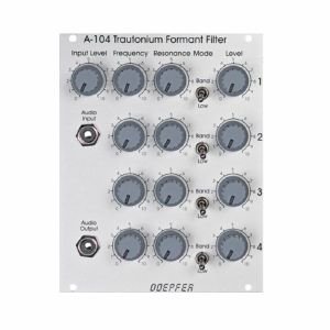
Doepfer A-104 Trautonium Formant Filter Module (filter/equalizer module)
Cat: 692505 Rel: 18 Jun 18
Quad resonance filter module - 20HP
Notes: A-104 is a fourfold formant filter as used in the Mixtur Trautonium by Oskar Sala. It is made of four parallel resonance filters, each filter can be switched to low pass or band pass or off. Frequency, resonance and level are controlled for each filter separately (no voltage control). The frequency range for the filters is about 50Hz...5kHz. The filter audio inputs are very sensitive so that distortion may intentionally be used to create new sounds - if desired. The sketch below shows the basic layout of the A-104. The A-104 is a versatile module for sound modification. In the first place it is used for reproduction of resonances (e.g. the vocal-like effects known from the Trautonium). In combination with the subharmonic generator A-113, the Trautonium Manual A-198 and some other A-100 modules one obtains a Trautonium replica. More detailed information about the Trautonium can be found on our internet site.
Dimensions
20 HP
45 mm deep
Current Draw
30 mA +12V
10 mA -12V
… Read moreDimensions
20 HP
45 mm deep
Current Draw
30 mA +12V
10 mA -12V
out of stock $131.74
Otros clientes también compraron...
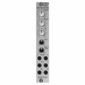
Doepfer A-105-2 24dB Low Pass (SSI-Type) Filter Module (silver) (filter/oscillator synth module)
Cat: 973741 Rel: 14 Nov 23
24dB SSI low pass filter - 4HP.
Notes: Module A-105-2 is a voltage controlled low pass filter with 24dB/octave slope.
It is the successor of the A-105 which had to be discontinued because the obsolete SSM2044 filter circuit. The A-105-2 is based on the SSI2144 which is in turn the successor circuit of the SSM2044. The features of both modules are nearly the same. The main difference is the clearly reduced front panel width of the A-105-2 (4HP instead of 8HP) and the associated changes of the controls and sockets positions. In addition the A-105-2 is equipped with 2 audio inputs.
The module has these controls and in/outputs available:
Control Frequ: manual frequency control
Control FCV2: attenuator for the frequency control voltage applied to socket FCV2
Control Q: manual resonance control
Control QCV: attenuator for the resonance control voltage applied to socket QCV
Control Input 1 Level: attenuator for the audio input signal applied to socket Input 1
Socket Input 1: audio input 1 (with attenuator)
Socket Input 2: audio input 2 (without attenuator)
Socket FCV1: frequency control voltage 1 (without attenuator, about 1V/oct scale)
Socket FCV2: frequency control voltage 2 (with attenuator)
Socket QCV: resonance control voltage (with attenuator)
Socket Out: audio output
Technical notes:
Frequency range: about 15Hz ... 15 kHz
Resonance up to self oscillation
Max. input voltage at Input 2 without clipping/distortion: about 15Vpp
Max. output voltage without clipping/distortion: about 15Vpp
The signals of both inputs are mixed before they are processed by the filter. This saves an external mixer for small setups.
Depth: 45 mm
HP : 4
… Read moreIt is the successor of the A-105 which had to be discontinued because the obsolete SSM2044 filter circuit. The A-105-2 is based on the SSI2144 which is in turn the successor circuit of the SSM2044. The features of both modules are nearly the same. The main difference is the clearly reduced front panel width of the A-105-2 (4HP instead of 8HP) and the associated changes of the controls and sockets positions. In addition the A-105-2 is equipped with 2 audio inputs.
The module has these controls and in/outputs available:
Control Frequ: manual frequency control
Control FCV2: attenuator for the frequency control voltage applied to socket FCV2
Control Q: manual resonance control
Control QCV: attenuator for the resonance control voltage applied to socket QCV
Control Input 1 Level: attenuator for the audio input signal applied to socket Input 1
Socket Input 1: audio input 1 (with attenuator)
Socket Input 2: audio input 2 (without attenuator)
Socket FCV1: frequency control voltage 1 (without attenuator, about 1V/oct scale)
Socket FCV2: frequency control voltage 2 (with attenuator)
Socket QCV: resonance control voltage (with attenuator)
Socket Out: audio output
Technical notes:
Frequency range: about 15Hz ... 15 kHz
Resonance up to self oscillation
Max. input voltage at Input 2 without clipping/distortion: about 15Vpp
Max. output voltage without clipping/distortion: about 15Vpp
The signals of both inputs are mixed before they are processed by the filter. This saves an external mixer for small setups.
Depth: 45 mm
HP : 4
1 in stock $109.79
Otros clientes también compraron...
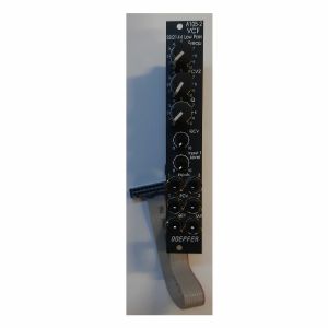
Doepfer A-105-2v 24dB Low Pass (SSI-Type) Filter Vintage Edition Module (black) (filter/oscillator synth module)
Cat: 973745 Rel: 14 Nov 23
24dB SSI low pass filter module - 4HP.
Notes: Module A-105-2V is a voltage controlled low pass filter with 24dB/octave slope.
It is the successor of the A-105 which had to be discontinued because the obsolete SSM2044 filter circuit. The A-105-2 is based on the SSI2144 which is in turn the successor circuit of the SSM2044. The features of both modules are nearly the same. The main difference is the clearly reduced front panel width of the A-105-2 (4HP instead of 8HP) and the associated changes of the controls and sockets positions. In addition the A-105-2 is equipped with 2 audio inputs.
The module has these controls and in/outputs available:
Control Frequ: manual frequency control
Control FCV2: attenuator for the frequency control voltage applied to socket FCV2
Control Q: manual resonance control
Control QCV: attenuator for the resonance control voltage applied to socket QCV
Control Input 1 Level: attenuator for the audio input signal applied to socket Input 1
Socket Input 1: audio input 1 (with attenuator)
Socket Input 2: audio input 2 (without attenuator)
Socket FCV1: frequency control voltage 1 (without attenuator, about 1V/oct scale)
Socket FCV2: frequency control voltage 2 (with attenuator)
Socket QCV: resonance control voltage (with attenuator)
Socket Out: audio output
Technical notes:
Frequency range: about 15Hz ... 15 kHz
Resonance up to self oscillation
Max. input voltage at Input 2 without clipping/distortion: about 15Vpp
Max. output voltage without clipping/distortion: about 15Vpp
The signals of both inputs are mixed before they are processed by the filter. This saves an external mixer for small setups.
Depth: 45 mm
HP : 4
… Read moreIt is the successor of the A-105 which had to be discontinued because the obsolete SSM2044 filter circuit. The A-105-2 is based on the SSI2144 which is in turn the successor circuit of the SSM2044. The features of both modules are nearly the same. The main difference is the clearly reduced front panel width of the A-105-2 (4HP instead of 8HP) and the associated changes of the controls and sockets positions. In addition the A-105-2 is equipped with 2 audio inputs.
The module has these controls and in/outputs available:
Control Frequ: manual frequency control
Control FCV2: attenuator for the frequency control voltage applied to socket FCV2
Control Q: manual resonance control
Control QCV: attenuator for the resonance control voltage applied to socket QCV
Control Input 1 Level: attenuator for the audio input signal applied to socket Input 1
Socket Input 1: audio input 1 (with attenuator)
Socket Input 2: audio input 2 (without attenuator)
Socket FCV1: frequency control voltage 1 (without attenuator, about 1V/oct scale)
Socket FCV2: frequency control voltage 2 (with attenuator)
Socket QCV: resonance control voltage (with attenuator)
Socket Out: audio output
Technical notes:
Frequency range: about 15Hz ... 15 kHz
Resonance up to self oscillation
Max. input voltage at Input 2 without clipping/distortion: about 15Vpp
Max. output voltage without clipping/distortion: about 15Vpp
The signals of both inputs are mixed before they are processed by the filter. This saves an external mixer for small setups.
Depth: 45 mm
HP : 4
out of stock $109.79
Otros clientes también compraron...
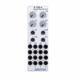
Doepfer A-105-4 Quad Poly SSM VCF Polyphonic Filter Module (filter/quad synth module)
Cat: 676691 Rel: 21 Sep 18
Polyphonic filter with four identical 24dB Lowpass filters 8HP
Notes: A-105-4 is our first polyphonic filter and contains four
identical 24dB Lowpass filters (SSM2044 type). It has
available common manual controls and CV inputs with
attenuators for these parameters:
Frequency (F)
Frequency Modulation Intensity (FM)
Resonance (Q)
Audio Input Level (L)
Each filter has available a separate FM input as well as an Audio Input and Output. The FM input is typically connected to the output of the associated envelope generator (e.g. A-141-4).
The envelope amount for all four filters is controlled by the FM knob and the CVFM input by means of four built-in VCAs, which are controlled by the FM control and CVFM input. This allows also voltage control of the envelope amounts.
In addition common frequency modulation for all filters is possible (e.g. by an LFO). For this the CVF input with attenuator can be used. The range of the audio input level control (L) allows also clipping/distortion with typical A-100 audio levels
(e.g. from A-111-4) at the filter inputs. Even this parameter is voltage controllable as well as the resonance (Q).
Application: polyphonic patches (four VCFs with same parameters).
… Read moreidentical 24dB Lowpass filters (SSM2044 type). It has
available common manual controls and CV inputs with
attenuators for these parameters:
Frequency (F)
Frequency Modulation Intensity (FM)
Resonance (Q)
Audio Input Level (L)
Each filter has available a separate FM input as well as an Audio Input and Output. The FM input is typically connected to the output of the associated envelope generator (e.g. A-141-4).
The envelope amount for all four filters is controlled by the FM knob and the CVFM input by means of four built-in VCAs, which are controlled by the FM control and CVFM input. This allows also voltage control of the envelope amounts.
In addition common frequency modulation for all filters is possible (e.g. by an LFO). For this the CVF input with attenuator can be used. The range of the audio input level control (L) allows also clipping/distortion with typical A-100 audio levels
(e.g. from A-111-4) at the filter inputs. Even this parameter is voltage controllable as well as the resonance (Q).
Application: polyphonic patches (four VCFs with same parameters).
out of stock $205.31
Otros clientes también compraron...
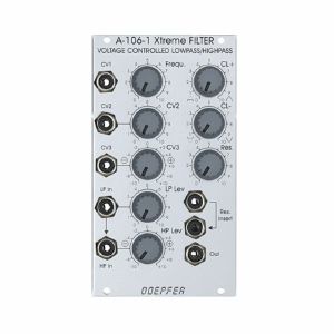
Doepfer A-106-1 Xtreme Filter Voltage Controlled Lowpass/Highpass Filter Module (modular synthesiser)
Cat: 692507 Rel: 19 Jun 18
Voltage controlled lowpass/highpass filter module - 14HP
Notes: Module A-106-1 has it's origin in our experiments to built a MS20 filter clone. The module is not exactly the same as the MS20 filter but similar. The famous original MS20 included two filters: a 12 dB lowpass and a 6dB high pass filter connected in series both with a very special design (the MS20 highpass if very often described as 12dB high pass, but this is not true). During our researches we found a way to use the same circuit simultaneously as lowpass and highpass for 2 different audio signals (a bit similar to the A-101-1 Steiner Vactrol filter that has even different audio inputs available, but with the special MS20 circuit). For this two separate audio inputs for lowpass (LP) and highpass (HP) with separate level controls are available. The sockets are normalled, i.e. the signal applied to the LP input is available for the HP input too provided that no plug is inserted into the HP input socket. The level control of the HP input is realized as a polarized input. This means that the signal can be added with the same polarity (+ range) or opposite polarity (- range) compared to the LP input. This feature enables notch (+) and bandpass (-) filter functions too. From our point of view this is the most flexible solution that enables e.g. these functions:
Lowpass: the audio signal is fed to the LP input, HP level control is set to zero, LP level control is set to the desired level
Highpass: the audio signal is fed to the LP or HP input, LP level control is set to zero, HP level control is set to the desired level (in this special case it does not matter if positive or negative amplification is chosen with the polarizer control)
Lowpass/highpass mix with one audio signal: the audio signal is fed to the LP input, LP and HP level controls are set to the desired levels.
special setting 1: if the level controls for LP and HP are set in a way that both levels are identical with the same polarity (i.e. + range of the HP level control) and no or little distortion only one obtains ~ a notch filter (the "~" indicates that the notch is far from beeing perfect, the attenuation in the passband is not as good as for other filters of the A-100 system, look at the frequency response curves at the bottom of this decoment for details)
special setting 2: if the level controls for LP and HP are set in a way that both levels are identical with the opposite polarity (i.e. - range of the HP level control) and no or little distortion only one obtains ~ a bandpass filter (the "~" indicates that even the bandpass is far from beeing perfect, there is a significant feedthrough of frequencies below and above the center frequency, look at the frequency response curves at the bottom of this decoment for details)
Remark for settings 1 and 2: The original MS20 circuit was not planned for notch or bandpass applications. The ~notch and ~bandpass filters should be treated as a free bonus and have the disadvantages mentioned above. The reason is that the lowpass has a 12dB/octave slope and the highpass 6dB/octave. This leads to phase relations that do not allow a "perfect" bandpass and notch simply by adding/subtracting signals as for other filter designs (for insiders: there remains always a 90 degree phase shift). For better notches and bandpasses other A-100 filters should be used - or two A-106-1 patched in series (bandpass) or parallel (notch) with suitable frequency settings.
Lowpass and highpass with two different audio signals: the two audio signals are fed to the LP input resp. HP input, the level controls for LP and HP are set to the desired levels. For the +/- control of the HP input it is essential in this case if the two input signals are phase correlated (e.g. two different outputs of the same VCO or VCO output and a frequency divided signal derived from this VCO) or there is no fixed phase correlation between the two signals (e.g. two different VCOs). In the first case the the - and + range of the HP control leads to different filter results. In the second case there is no difference if the + or - range of the HP control is used.
This design allows even some very special functions: It is e.g. possible to adjust the controls so that the LP signal does not distort but the HP share does (or the other way round) - alternatively with the same or opposite polarity compared to the LP signal. For this the LP level has to be set to a small value so that the signal does not distort. The HP level control has to be set to a higher value (in the + or - range) so that the HP share will distort.
The variety of controls allows a lot of functions that are not available for any other filter we know.
During the A-106-1 development we found also that it might be useful to add controls not available in the original filter design. In the original circuit the filter output level is limited to about +/- 0.7V by two antiparallel diodes across the output/resonance amplifier. By chance we discovered that removing one or both diodes leads to noticeable different behaviour of the filter. Moreover we added two rotary controls CL+ and CL- to adjust the effect of each limiting diode (from original filter behaviour, i.e. fully active limiting diodes, to no limiting effect). The independent control for each diode allows asymmetrical limiting/amplification that causes a completely new and sometimes very strange behaviour. One of the main effects of the asymmetrical limiting is that in self-oscillation the filter does not generate a sine wave but short pulses if only one of the limiting diodes is activated. Another effect is that a higher output of the filter can be obtained (limited to about +/- 0.7V for the original circuit). In addition dirty noise effects appear at certain combinations of the control settings for resonance, CL+, CL- and input level. The controls CL+, CL-, Resonance, LP level and HP level have be looked at always in a common context: if the input levels are small the CL+ and CL- controls will have no effect as the signal does not distort at all. Increasing the resonance also increases the audio level and the CL+/CL- controls may now have an effect without changing the input level ! Same applies if the resonance control remains unchanged but the input level is increases. Now the CL+ or CL- control will have an effect as the level reaches the clipping thresholds. Increasing the audio level does also suppress the resonance if distortion becomes extreme. The "teamwork" of the five controls is very complex and has to be learned by doing and hearing.
The audio inputs are very sensitive to allow even extrem distortion effects, much more than possible with the original filter design.
We also expanded the module by an insert option for the resonance feedback loop. This allows to insert other A-100 modules into the resonance circuit. The standard application is to insert a VCA for voltage controlled resonance. But even other modules - e.g. waveshaper, divider, phaser, distortion, PLL, wave multiplier, spring reverb, ring modulator, frequency shifter ony any other audio processing module - can be inserted to obtain sounds you have never heard before.
On top of this the module is equipped with two frequency CV inputs. One is carried out as a polarizer. This means that effect of the external CV (e.g. envelope from an ADSR A-140 or A-141) to the filter frequency is positive (+ range) or negative (- range). Especially when the filter is moved from LP to HP it might be useful to invert the polarity of the envelope CV. We also have to mention that the frequency response if far from 1V/oct but rather non-linear.
To obtain the filter section of the original MS20 two A-106-1 have to be patched in series (one in LP mode, the other in HP mode, both with CL+ and CL- set to zero).
It has to be pointed out that the A-106-1 is far away from being a "perfect" filter in an academic sense: The control scale is non-linear. With self-oscillation all sorts of waveforms except sine are generated. With high distortion and resonance settings a lot of roaring/rattling/noise or other unpredictable sounds may appear. High distortion/level may "kill" the resonance at certain settings. The filter has a significant control voltage feedthrough and is noisy. The "bandpass" is not a real band pass as a considerable share of all frequencies passes through. The notch filter does attenuate only about 50% at the center frequency - and many more. But the A-106-1 has a lot of character - much more than any other filter of the A-100. It is a very strange and awesome filter - somehow exactly the contrast to the A-108, which is a very smooth, warm and predictable filter. The A-106-1 is definitely not the right choice for "moogish" and "civilized" sounds but for extreme, exceptional and experimental sounds - this is why we call the module "X-Filter". If you want to know more technical details please look at the A-101-1 technical details. In this document the basics of the A-101-1 (Steiner) and A-106-1 filter are described.
Included options: For the HP input control can be chosen if the polarizer is active or if a normal attenuator is available. For some applications it might be useful to have the level controls of LP and LP work in the same way (e.g. to obtain the same level for both inputs). With a jumper on the pc board the type of HP level control can be chosen. The CL+ and CL- parameters are prepared to be controlled by external vactrols. Two pin headers are used to establish a connection to the universal vactrol module that is still under development. This will allow voltage control of the CL+ and CL- parameter.
Width: 14HP / 70.8 mm
Depth: 40 mm (measured from the rear side of the front panel)
Current: +30mA (+12V) / -20mA (-12V)
… Read moreLowpass: the audio signal is fed to the LP input, HP level control is set to zero, LP level control is set to the desired level
Highpass: the audio signal is fed to the LP or HP input, LP level control is set to zero, HP level control is set to the desired level (in this special case it does not matter if positive or negative amplification is chosen with the polarizer control)
Lowpass/highpass mix with one audio signal: the audio signal is fed to the LP input, LP and HP level controls are set to the desired levels.
special setting 1: if the level controls for LP and HP are set in a way that both levels are identical with the same polarity (i.e. + range of the HP level control) and no or little distortion only one obtains ~ a notch filter (the "~" indicates that the notch is far from beeing perfect, the attenuation in the passband is not as good as for other filters of the A-100 system, look at the frequency response curves at the bottom of this decoment for details)
special setting 2: if the level controls for LP and HP are set in a way that both levels are identical with the opposite polarity (i.e. - range of the HP level control) and no or little distortion only one obtains ~ a bandpass filter (the "~" indicates that even the bandpass is far from beeing perfect, there is a significant feedthrough of frequencies below and above the center frequency, look at the frequency response curves at the bottom of this decoment for details)
Remark for settings 1 and 2: The original MS20 circuit was not planned for notch or bandpass applications. The ~notch and ~bandpass filters should be treated as a free bonus and have the disadvantages mentioned above. The reason is that the lowpass has a 12dB/octave slope and the highpass 6dB/octave. This leads to phase relations that do not allow a "perfect" bandpass and notch simply by adding/subtracting signals as for other filter designs (for insiders: there remains always a 90 degree phase shift). For better notches and bandpasses other A-100 filters should be used - or two A-106-1 patched in series (bandpass) or parallel (notch) with suitable frequency settings.
Lowpass and highpass with two different audio signals: the two audio signals are fed to the LP input resp. HP input, the level controls for LP and HP are set to the desired levels. For the +/- control of the HP input it is essential in this case if the two input signals are phase correlated (e.g. two different outputs of the same VCO or VCO output and a frequency divided signal derived from this VCO) or there is no fixed phase correlation between the two signals (e.g. two different VCOs). In the first case the the - and + range of the HP control leads to different filter results. In the second case there is no difference if the + or - range of the HP control is used.
This design allows even some very special functions: It is e.g. possible to adjust the controls so that the LP signal does not distort but the HP share does (or the other way round) - alternatively with the same or opposite polarity compared to the LP signal. For this the LP level has to be set to a small value so that the signal does not distort. The HP level control has to be set to a higher value (in the + or - range) so that the HP share will distort.
The variety of controls allows a lot of functions that are not available for any other filter we know.
During the A-106-1 development we found also that it might be useful to add controls not available in the original filter design. In the original circuit the filter output level is limited to about +/- 0.7V by two antiparallel diodes across the output/resonance amplifier. By chance we discovered that removing one or both diodes leads to noticeable different behaviour of the filter. Moreover we added two rotary controls CL+ and CL- to adjust the effect of each limiting diode (from original filter behaviour, i.e. fully active limiting diodes, to no limiting effect). The independent control for each diode allows asymmetrical limiting/amplification that causes a completely new and sometimes very strange behaviour. One of the main effects of the asymmetrical limiting is that in self-oscillation the filter does not generate a sine wave but short pulses if only one of the limiting diodes is activated. Another effect is that a higher output of the filter can be obtained (limited to about +/- 0.7V for the original circuit). In addition dirty noise effects appear at certain combinations of the control settings for resonance, CL+, CL- and input level. The controls CL+, CL-, Resonance, LP level and HP level have be looked at always in a common context: if the input levels are small the CL+ and CL- controls will have no effect as the signal does not distort at all. Increasing the resonance also increases the audio level and the CL+/CL- controls may now have an effect without changing the input level ! Same applies if the resonance control remains unchanged but the input level is increases. Now the CL+ or CL- control will have an effect as the level reaches the clipping thresholds. Increasing the audio level does also suppress the resonance if distortion becomes extreme. The "teamwork" of the five controls is very complex and has to be learned by doing and hearing.
The audio inputs are very sensitive to allow even extrem distortion effects, much more than possible with the original filter design.
We also expanded the module by an insert option for the resonance feedback loop. This allows to insert other A-100 modules into the resonance circuit. The standard application is to insert a VCA for voltage controlled resonance. But even other modules - e.g. waveshaper, divider, phaser, distortion, PLL, wave multiplier, spring reverb, ring modulator, frequency shifter ony any other audio processing module - can be inserted to obtain sounds you have never heard before.
On top of this the module is equipped with two frequency CV inputs. One is carried out as a polarizer. This means that effect of the external CV (e.g. envelope from an ADSR A-140 or A-141) to the filter frequency is positive (+ range) or negative (- range). Especially when the filter is moved from LP to HP it might be useful to invert the polarity of the envelope CV. We also have to mention that the frequency response if far from 1V/oct but rather non-linear.
To obtain the filter section of the original MS20 two A-106-1 have to be patched in series (one in LP mode, the other in HP mode, both with CL+ and CL- set to zero).
It has to be pointed out that the A-106-1 is far away from being a "perfect" filter in an academic sense: The control scale is non-linear. With self-oscillation all sorts of waveforms except sine are generated. With high distortion and resonance settings a lot of roaring/rattling/noise or other unpredictable sounds may appear. High distortion/level may "kill" the resonance at certain settings. The filter has a significant control voltage feedthrough and is noisy. The "bandpass" is not a real band pass as a considerable share of all frequencies passes through. The notch filter does attenuate only about 50% at the center frequency - and many more. But the A-106-1 has a lot of character - much more than any other filter of the A-100. It is a very strange and awesome filter - somehow exactly the contrast to the A-108, which is a very smooth, warm and predictable filter. The A-106-1 is definitely not the right choice for "moogish" and "civilized" sounds but for extreme, exceptional and experimental sounds - this is why we call the module "X-Filter". If you want to know more technical details please look at the A-101-1 technical details. In this document the basics of the A-101-1 (Steiner) and A-106-1 filter are described.
Included options: For the HP input control can be chosen if the polarizer is active or if a normal attenuator is available. For some applications it might be useful to have the level controls of LP and LP work in the same way (e.g. to obtain the same level for both inputs). With a jumper on the pc board the type of HP level control can be chosen. The CL+ and CL- parameters are prepared to be controlled by external vactrols. Two pin headers are used to establish a connection to the universal vactrol module that is still under development. This will allow voltage control of the CL+ and CL- parameter.
Width: 14HP / 70.8 mm
Depth: 40 mm (measured from the rear side of the front panel)
Current: +30mA (+12V) / -20mA (-12V)
out of stock $120.76
Otros clientes también compraron...
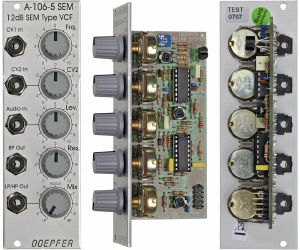
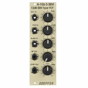
Doepfer A-106-5 SEM 12dB SEM Type VCF Module (silver) (filter synth module)
Cat: 577753 Rel: 06 Jun 19
12dB multi-mode filter - 8HP
Notes: Module A-106-5 is a 12dB multimode filter that is based on the filter circuit of the Oberheim SEM module.
The filter is equipped with a band pass output and a combined low/notch/high pass output. For this output a control knob defines the relation between low and high pass signal. If both signals appear at the same level (i.e. middle position of the Mix knob) one obtains a notch filter. Otherwise the low or high pass signal predominates.
The module does not feature self-oscillation in contrast to most of the other filters of the A-100 system.
The module generates a distorted audio signal if the level control is set to about 50% (i.e. centre position) or more with A-100 standard signals like VCOs.
… Read moreThe filter is equipped with a band pass output and a combined low/notch/high pass output. For this output a control knob defines the relation between low and high pass signal. If both signals appear at the same level (i.e. middle position of the Mix knob) one obtains a notch filter. Otherwise the low or high pass signal predominates.
The module does not feature self-oscillation in contrast to most of the other filters of the A-100 system.
The module generates a distorted audio signal if the level control is set to about 50% (i.e. centre position) or more with A-100 standard signals like VCOs.
1 in stock $90.02
Otros clientes también compraron...
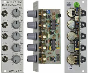
Doepfer A-106-5 SEM 12dB SEM Type VCF Module (silver) (B-STOCK) (filter synth module)
Cat: 935425 Rel: 06 Jun 19
B-STOCK: Item refurbished, repaired and in perfect working order.
Notes: ***B-STOCK: Item refurbished, repaired and in perfect working order.***
Module A-106-5 is a 12dB multimode filter that is based on the filter circuit of the Oberheim SEM module.
The filter is equipped with a band pass output and a combined low/notch/high pass output. For this output a control knob defines the relation between low and high pass signal. If both signals appear at the same level (i.e. middle position of the Mix knob) one obtains a notch filter. Otherwise the low or high pass signal predominates.
The module does not feature self-oscillation in contrast to most of the other filters of the A-100 system.
The module generates a distorted audio signal if the level control is set to about 50% (i.e. centre position) or more with A-100 standard signals like VCOs.
… Read moreModule A-106-5 is a 12dB multimode filter that is based on the filter circuit of the Oberheim SEM module.
The filter is equipped with a band pass output and a combined low/notch/high pass output. For this output a control knob defines the relation between low and high pass signal. If both signals appear at the same level (i.e. middle position of the Mix knob) one obtains a notch filter. Otherwise the low or high pass signal predominates.
The module does not feature self-oscillation in contrast to most of the other filters of the A-100 system.
The module generates a distorted audio signal if the level control is set to about 50% (i.e. centre position) or more with A-100 standard signals like VCOs.
out of stock $80.41
Otros clientes también compraron...
Doepfer A-106-5 SEM 12dB SEM Type VCF Special Edition Module (cream) (filter synth module)
Cat: 671592 Rel: 29 Nov 17
12dB multi-mode filter based on classic SEM filter circuitry
Notes: Module A-106-5 is a 12dB multimode filter that is based on the filter circuit of the Oberheim SEM module. The filter is equipped with a band pass output and a combined low/notch/high pass output. For this output a control knob defines the relation between low and high pass signal. If both signals appear at the same level (i.e. middle position of the Mix knob) one obtains a notch filter. Otherwise the low or high pass signal predominates. The module does not feature self oscillation in contrast to most of the other filters of the A-100 system. The module generates a distorted audio signal if the level control is set to about 50% (i.e. centre position) or more with A-100 standard signals like VCOs.
Inputs: Audio In, CV1 In without attenuator, CV2 In with Polarizer
Outputs: Bandpass Out, Low/Highpass Mix-Out
Controls: Audio Attenuator, CV2 Polarizer, Frequency, Resonance, LP/HP Mix
The function and operation of this module is very similar to the Wasp filter module A-124. But the sound of both filters is very different! We will publish no separate user's manual for the A-106-5 but a combined manual for both A-106-5 and A-124. The only functional difference is the position of the sockets and controls, and the function of the controls CV2 (A-124: normal attenuator, A-106-5: polarizer)
Width: 8HP / 40.3mm
Depth: 55mm (Measured from the rear side of the front panel)
Current: +12V: +30mA, -12V: -20mA
… Read moreInputs: Audio In, CV1 In without attenuator, CV2 In with Polarizer
Outputs: Bandpass Out, Low/Highpass Mix-Out
Controls: Audio Attenuator, CV2 Polarizer, Frequency, Resonance, LP/HP Mix
The function and operation of this module is very similar to the Wasp filter module A-124. But the sound of both filters is very different! We will publish no separate user's manual for the A-106-5 but a combined manual for both A-106-5 and A-124. The only functional difference is the position of the sockets and controls, and the function of the controls CV2 (A-124: normal attenuator, A-106-5: polarizer)
Width: 8HP / 40.3mm
Depth: 55mm (Measured from the rear side of the front panel)
Current: +12V: +30mA, -12V: -20mA
out of stock $83.44
Otros clientes también compraron...
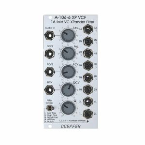
Doepfer A-106-6 XP VCF 16-Fold VC Xpander Filter Module (silver) (filter/oscillator module)
Cat: 692508 Rel: 19 Jun 18
Multimode filter based on the filter circuit of the Oberheim Xpander - 12HP
Notes: Module A-106-6 is a multimode filter that is based on the filter circuit of the Oberheim Xpander. The module features 15 different filter types (those filters of the A-107 that were available in the Xpander) with 8 filters available simultaneously. The toggle switch Filter Group is used to switch between 2 filter groups.
These filter types are available:
- 1L (6 dB low pass)
- 2L (12 dB low pass)
- 3L (18 dB low pass)
- 4L (24 dB low pass)
- 1H (6 dB high pass)
- 2H (12 dB high pass)
- 3H (18 dB high pass)
- 2B (6 dB band pass)
- 4B (12 dB bandpass)
- 2N (notch)
- 3A (allpass)
- 2H1L (asymmetrical band pass made of a 12 dB high pass and a 6 dB low pass)
- 3H1L (asymmetrical band pass made of a 18 dB high pass and a 6 dB low pass)
- 2N1L (combination of notch and 6 dB low pass)
- 3A1L (combination of allpass and 6 dB low pass)
The module features voltage-controlled resonance. For filter group 2 (2L, 4L, 2B ...) even self-oscillation is possible.
All standard VCF controls are available: manual filter frequency control Frq, one control voltage input with attenuator (FCV2) and one without attenuator (FCV1, ~ 1 V/octave). In addition, voltage-controlled resonance with manual control (Q) and a CV input with attenuator (QCV) are available.
The circuit is based on a 24dB lowpass filter. The outputs of the four internal filter stages (i.e. the 6, 12, 18 and 24dB outputs) are mixed together with different levels and polarities to obtain 15 different filters. Because of this special circuit the outputs have slightly different levels and noise floor. This is caused by the different internal amplifications and numbers of stages that are required to generate the filter in question. If e.g. a filter is derived by one stage only (e.g. the 6 dB, 12dB, 18dB and 24dB low pass) the noise floor is smaller compared to a filter that is derived by a combination of all four filter stages.
… Read moreThese filter types are available:
- 1L (6 dB low pass)
- 2L (12 dB low pass)
- 3L (18 dB low pass)
- 4L (24 dB low pass)
- 1H (6 dB high pass)
- 2H (12 dB high pass)
- 3H (18 dB high pass)
- 2B (6 dB band pass)
- 4B (12 dB bandpass)
- 2N (notch)
- 3A (allpass)
- 2H1L (asymmetrical band pass made of a 12 dB high pass and a 6 dB low pass)
- 3H1L (asymmetrical band pass made of a 18 dB high pass and a 6 dB low pass)
- 2N1L (combination of notch and 6 dB low pass)
- 3A1L (combination of allpass and 6 dB low pass)
The module features voltage-controlled resonance. For filter group 2 (2L, 4L, 2B ...) even self-oscillation is possible.
All standard VCF controls are available: manual filter frequency control Frq, one control voltage input with attenuator (FCV2) and one without attenuator (FCV1, ~ 1 V/octave). In addition, voltage-controlled resonance with manual control (Q) and a CV input with attenuator (QCV) are available.
The circuit is based on a 24dB lowpass filter. The outputs of the four internal filter stages (i.e. the 6, 12, 18 and 24dB outputs) are mixed together with different levels and polarities to obtain 15 different filters. Because of this special circuit the outputs have slightly different levels and noise floor. This is caused by the different internal amplifications and numbers of stages that are required to generate the filter in question. If e.g. a filter is derived by one stage only (e.g. the 6 dB, 12dB, 18dB and 24dB low pass) the noise floor is smaller compared to a filter that is derived by a combination of all four filter stages.
out of stock $152.61
Otros clientes también compraron...
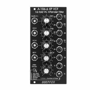
Doepfer A-106-6V 16-Fold VC XPander Filter Vintage Edition Module (black) (filter synth module)
Cat: 790473 Rel: 30 Oct 20
Multimode filter module
Notes: Module A-106-6 is a multimode filter that is based on the filter circuit of the Oberheim Xpander. The module features 15 different filter types with 8 filters available simultaneously.
The toggle switch Filter Group is used to switch between 2 filter groups. These filter types are available:
1L (6 dB low pass)
2L (12 dB low pass)
3L (18 dB low pass)
4L (24 dB low pass)
1H (6 dB high pass)
2H (12 dB high pass)
3H (18 dB high pass)
2B (6 dB band pass)
4B (12 dB bandpass)
2N (notch)
3A (allpass)
2H1L (asymmetrical band pass made of a 12 dB high pass and a 6 dB low pass)
3H1L (asymmetrical band pass made of a 18 dB high pass and a 6 dB low pass)
2N1L (combination of notch and 6 dB low pass)
3A1L (combination of allpass and 6 dB low pass)
The module features voltage controlled resonance. For filter group 2 (2L, 4L, 2B ...) even self oscillation is possible. All standard VCF controls are available: manual filter frequency control Frq, one control voltage input with attenuator (FCV2)and one without attenuator (FCV1, ~ 1 V/octave). In addition voltage controlled resonance with manual control (Q) and a CV input with attenuator (QCV) are available. The circuit is based on a 24dB lowpass filter. The outputs of the four internal filter stages (i.e. the 6, 12, 18 and 24dB outputs) are mixed together with different levels and polarities to obtain 15 different filters. Because of this special circuit the outputs have slightly different levels and noise floor. This is caused by the different internal amplifications and numbers of stages that are required to generate the filter in question. If e.g. a filter is derived by one stage only (e.g. the 6 dB, 12dB, 18dB and 24dB low pass) the noise floor is smaller compared to a filter that is derived by a combination of all four filter stages. The module generates a distorted audio signal if the level control is set to about 50% (i.e. center position) or more with A-100 standard signals like VCOs.
Power consumption: 50mA at +12V and 50mA at -12V
Depth: 50mm
HP : 12
… Read moreThe toggle switch Filter Group is used to switch between 2 filter groups. These filter types are available:
1L (6 dB low pass)
2L (12 dB low pass)
3L (18 dB low pass)
4L (24 dB low pass)
1H (6 dB high pass)
2H (12 dB high pass)
3H (18 dB high pass)
2B (6 dB band pass)
4B (12 dB bandpass)
2N (notch)
3A (allpass)
2H1L (asymmetrical band pass made of a 12 dB high pass and a 6 dB low pass)
3H1L (asymmetrical band pass made of a 18 dB high pass and a 6 dB low pass)
2N1L (combination of notch and 6 dB low pass)
3A1L (combination of allpass and 6 dB low pass)
The module features voltage controlled resonance. For filter group 2 (2L, 4L, 2B ...) even self oscillation is possible. All standard VCF controls are available: manual filter frequency control Frq, one control voltage input with attenuator (FCV2)and one without attenuator (FCV1, ~ 1 V/octave). In addition voltage controlled resonance with manual control (Q) and a CV input with attenuator (QCV) are available. The circuit is based on a 24dB lowpass filter. The outputs of the four internal filter stages (i.e. the 6, 12, 18 and 24dB outputs) are mixed together with different levels and polarities to obtain 15 different filters. Because of this special circuit the outputs have slightly different levels and noise floor. This is caused by the different internal amplifications and numbers of stages that are required to generate the filter in question. If e.g. a filter is derived by one stage only (e.g. the 6 dB, 12dB, 18dB and 24dB low pass) the noise floor is smaller compared to a filter that is derived by a combination of all four filter stages. The module generates a distorted audio signal if the level control is set to about 50% (i.e. center position) or more with A-100 standard signals like VCOs.
Power consumption: 50mA at +12V and 50mA at -12V
Depth: 50mm
HP : 12
out of stock $177.85
Otros clientes también compraron...
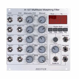
Doepfer A-107 Multitype Morphing Filter Module (synth module)
Cat: 692509 Rel: 18 Jun 18
Voltage controlled filter with 36 filter types - 26HP
Notes: This module contains 26 very different filter types which can be combined each after the other. You can morph or switch between those filter chains manually, with control voltage or with a clock signal. 15 filter types are known from the Oberheim Matrix 12 and there additional 21 new filter types.
The filters are organized in two groups of 18 filters each. The transition between different filter types within one group can be soft (morphing) or hard (switching).
The transition between the different filter types is controlled by two parameters: Filter Step (marked Step at the front panel) and Morphing Time (marked Morph at the front panel). For both parameters manual control, one CV input with attenuator and one CV input without attenuator are available.
The 36 filter types can be arranged in filter chains (resp. filter sequencer or filter orders) so that this sequence of filters is passed through while the control voltage changes from 0V to +5V. Each chain consists of 32 steps. 64 filter chains can be programmed by the user and stored in the non-volatile memory of the module.
Of course, the standard VCF controls are available: cut-off frequency and resonance. Both are voltage controllable. For the filters of the first group (1-18) self-oscillation is possible, the filters of the second group (19-36) do not feature self-oscillation.
The filter design is 100% analogue (CEM filter chip). Only the morphing control and memory managing is carried out by a microcontroller.
… Read moreThe filters are organized in two groups of 18 filters each. The transition between different filter types within one group can be soft (morphing) or hard (switching).
The transition between the different filter types is controlled by two parameters: Filter Step (marked Step at the front panel) and Morphing Time (marked Morph at the front panel). For both parameters manual control, one CV input with attenuator and one CV input without attenuator are available.
The 36 filter types can be arranged in filter chains (resp. filter sequencer or filter orders) so that this sequence of filters is passed through while the control voltage changes from 0V to +5V. Each chain consists of 32 steps. 64 filter chains can be programmed by the user and stored in the non-volatile memory of the module.
Of course, the standard VCF controls are available: cut-off frequency and resonance. Both are voltage controllable. For the filters of the first group (1-18) self-oscillation is possible, the filters of the second group (19-36) do not feature self-oscillation.
The filter design is 100% analogue (CEM filter chip). Only the morphing control and memory managing is carried out by a microcontroller.
out of stock $281.06
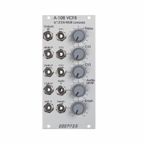
Otros clientes también compraron...
Doepfer A-108 6/12/24/48dB Low Pass Filter Module (filter synth module)
Cat: 692510 Rel: 19 Jun 18
Classic Moog voltage-controlled lowpass filter - 12HP
Notes: Module A-108 is a completely new voltage-controlled low pass filter based on the well-known transistor ladder (Moog ladder). The module has internally an 8-stage low pass filter with different slopes available: 6, 12, 18, 24, 30, 36, 42 and 48 dB per octave. In addition, it features a band pass output (i.e. band pass with transistor ladder). In the factory, the 4 low pass outputs of the A-108 are internally connected to the filter stages 6, 12, 24 and 48dB.
Resonance (Emphasis or Q) can be adjusted manually right up to self-oscillation, in which case the filter will behave like a sine wave oscillator. The A-108 features an external feedback input that enables the insertion of additional modules into the feedback path (e.g. VCA for voltage-controlled resonance or phaser/frequency shifter for phase/frequency shifting effects). The socket is normalized and internally connected to the 48dB low pass output if no cable is inserted into the feedback socket.
The frequency can be adjusted manually, or by voltage control. Three CV inputs (CV1, CV2, CV3) are available. CV2 and CV3 are equipped with attenuators.
The filter audio input is very sensitive so that distortion - if desired - is possible even with normal A-100 levels (e.g. VCO output). Self-oscillation will break off at high distortion levels as the internal feedback signal is drown out by the distorted audio signal. This feature may intentionally be used to create new sounds.
In combination with the Voltage Controlled Mixer A-135 and the Morphing Controller A-144 a filter with voltage-controlled slope can be realized (i.e. controlling the slope from 6dB to 48dB via CV).
… Read moreResonance (Emphasis or Q) can be adjusted manually right up to self-oscillation, in which case the filter will behave like a sine wave oscillator. The A-108 features an external feedback input that enables the insertion of additional modules into the feedback path (e.g. VCA for voltage-controlled resonance or phaser/frequency shifter for phase/frequency shifting effects). The socket is normalized and internally connected to the 48dB low pass output if no cable is inserted into the feedback socket.
The frequency can be adjusted manually, or by voltage control. Three CV inputs (CV1, CV2, CV3) are available. CV2 and CV3 are equipped with attenuators.
The filter audio input is very sensitive so that distortion - if desired - is possible even with normal A-100 levels (e.g. VCO output). Self-oscillation will break off at high distortion levels as the internal feedback signal is drown out by the distorted audio signal. This feature may intentionally be used to create new sounds.
In combination with the Voltage Controlled Mixer A-135 and the Morphing Controller A-144 a filter with voltage-controlled slope can be realized (i.e. controlling the slope from 6dB to 48dB via CV).
1 in stock $148.96
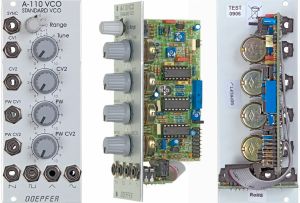
Otros clientes también compraron...
Doepfer A-110-1 Standard VCO Module (synth module)
Cat: 577769 Rel: 29 Nov 17
Standard VCO providing two CV inputs for pitch, an octave switch, four waveforms with separate outputs, pulse width modulation & hard sync - 10HP
Notes: Module A-110-1 is a voltage-controlled oscillator. This VCO's frequency range is about eight octaves (ca. 15Hz ... 8kHz). It can produce four waveforms simultaneously: rectangle, sawtooth, triangle, and sine wave (triangle and sine shapes are not perfect, see remark below). The output levels are typically 8Vpp for saw and rectangle, and 10Vpp for triangle and sine. The frequency or pitch of the VCO is determined by the position of the octave (Range) switch and tuning (Tune) knob, and by the voltage present at the CV inputs. Frequency modulation (FM) of the VCO is therefore a possibility. Footage (the octave of the fundamental) is set by the Range control in five steps, and Fine tuning controlled by the Tune knob by about +/-1 one semitone (can be modified for a wider range).
You can control the pulse width of the square wave either by hand, or by voltage control - Pulse Width Modulation or PWM.
For more detailed information please look at the user's manual A110_man.pdf. In addition, the A-110 service manual is available as an example for the A-100 service manual that is available at extra charges. This document describes also how to modify the sensitivity of the tune control, how to re-adjust the 1V/octave scale and the frequency offset (i.e. the absolute pitch). Such modifications should be carried out by experienced users only!
The core of the A-110-1 is a sawtooth oscillator (in contrast to the A-111-1, which is based on a triangle oscillator). The other waveforms are derived from the sawtooth by internal waveform converters. As the sawtooth reset (i.e. the back-to-zero slope) is not infinite fast but takes a little bit of time the derived waveforms triangle and sine are not perfect! At the top of the waveform they have a small glitch or notch that is caused by the sawtooth reset and cannot be eliminated by the waveform converters. The sine is derived from the triangle by a simple diode-based converter and the sine shape is not perfect (only a rounded triangle).
If a perfect triangle is required, the A-111-1 is recommended. For a perfect sine wave the quadrature LFO/VCO A-143-9 is recommended.
… Read moreYou can control the pulse width of the square wave either by hand, or by voltage control - Pulse Width Modulation or PWM.
For more detailed information please look at the user's manual A110_man.pdf. In addition, the A-110 service manual is available as an example for the A-100 service manual that is available at extra charges. This document describes also how to modify the sensitivity of the tune control, how to re-adjust the 1V/octave scale and the frequency offset (i.e. the absolute pitch). Such modifications should be carried out by experienced users only!
The core of the A-110-1 is a sawtooth oscillator (in contrast to the A-111-1, which is based on a triangle oscillator). The other waveforms are derived from the sawtooth by internal waveform converters. As the sawtooth reset (i.e. the back-to-zero slope) is not infinite fast but takes a little bit of time the derived waveforms triangle and sine are not perfect! At the top of the waveform they have a small glitch or notch that is caused by the sawtooth reset and cannot be eliminated by the waveform converters. The sine is derived from the triangle by a simple diode-based converter and the sine shape is not perfect (only a rounded triangle).
If a perfect triangle is required, the A-111-1 is recommended. For a perfect sine wave the quadrature LFO/VCO A-143-9 is recommended.
out of stock $142.72
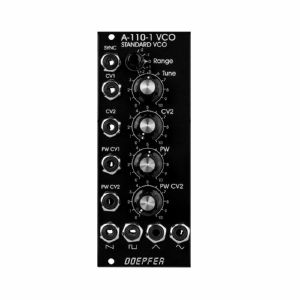
Otros clientes también compraron...
Doepfer A-110-1v Standard VCO Module (vintage edition) (synth module)
Cat: 692511 Rel: 19 Jun 18
Standard VCO providing two CV inputs for pitch, an octave switch, four waveforms with separate outputs, pulse width modulation & hard sync - 10HP
Notes: Module A-110-1 is a voltage-controlled oscillator. This VCO's frequency range is about eight octaves (ca. 15Hz ... 8kHz). It can produce four waveforms simultaneously: rectangle, sawtooth, triangle, and sine wave (triangle and sine shapes are not perfect, see remark below). The output levels are typically 8Vpp for saw and rectangle, and 10Vpp for triangle and sine. The frequency or pitch of the VCO is determined by the position of the octave (Range) switch and tuning (Tune) knob, and by the voltage present at the CV inputs. Frequency modulation (FM) of the VCO is therefore a possibility. Footage (the octave of the fundamental) is set by the Range control in five steps, and Fine tuning controlled by the Tune knob by about +/-1 one semitone (can be modified for a wider range).
You can control the pulse width of the square wave either by hand, or by voltage control - Pulse Width Modulation or PWM.
For more detailed information please look at the user's manual A110_man.pdf. In addition, the A-110 service manual is available as an example for the A-100 service manual that is available at extra charges. This document describes also how to modify the sensitivity of the tune control, how to re-adjust the 1V/octave scale and the frequency offset (i.e. the absolute pitch). Such modifications should be carried out by experienced users only!
The core of the A-110-1 is a sawtooth oscillator (in contrast to the A-111-1, which is based on a triangle oscillator). The other waveforms are derived from the sawtooth by internal waveform converters. As the sawtooth reset (i.e. the back-to-zero slope) is not infinite fast but takes a little bit of time the derived waveforms triangle and sine are not perfect! At the top of the waveform they have a small glitch or notch that is caused by the sawtooth reset and cannot be eliminated by the waveform converters. The sine is derived from the triangle by a simple diode-based converter and the sine shape is not perfect (only a rounded triangle).
If a perfect triangle is required, the A-111-1 is recommended. For a perfect sine wave the quadrature LFO/VCO A-143-9 is recommended.
… Read moreYou can control the pulse width of the square wave either by hand, or by voltage control - Pulse Width Modulation or PWM.
For more detailed information please look at the user's manual A110_man.pdf. In addition, the A-110 service manual is available as an example for the A-100 service manual that is available at extra charges. This document describes also how to modify the sensitivity of the tune control, how to re-adjust the 1V/octave scale and the frequency offset (i.e. the absolute pitch). Such modifications should be carried out by experienced users only!
The core of the A-110-1 is a sawtooth oscillator (in contrast to the A-111-1, which is based on a triangle oscillator). The other waveforms are derived from the sawtooth by internal waveform converters. As the sawtooth reset (i.e. the back-to-zero slope) is not infinite fast but takes a little bit of time the derived waveforms triangle and sine are not perfect! At the top of the waveform they have a small glitch or notch that is caused by the sawtooth reset and cannot be eliminated by the waveform converters. The sine is derived from the triangle by a simple diode-based converter and the sine shape is not perfect (only a rounded triangle).
If a perfect triangle is required, the A-111-1 is recommended. For a perfect sine wave the quadrature LFO/VCO A-143-9 is recommended.
out of stock $152.61
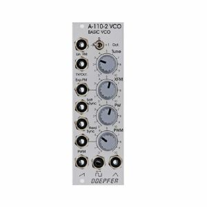
Otros clientes también compraron...
Doepfer A-110-2 Basic VCO Module (synth module)
Cat: 692512 Rel: 18 Jun 18
Basic voltage-controlled oscillator for the A-100 modular system
Notes: Module A-110-2 is a low-cost voltage-controlled oscillator. It's a slightly reduced version of the standard VCO A-110-1. Compared to the A-110-1, the A-110-2 has no sine output and the (expensive) octave rotary switch is replaced by a 3-position toggle switch. In return, the A-110-2 is equipped with an additional linear FM input and a soft sync input. A jumper is used to select the range of the tune control between about 1/2 octave and about 4 octaves. The width of the module is only 8 HP compared to the 10 HP of the A-110-1.
All other features are essentially the same as for the A-110-1.
Explanation of the jumpers and trimming potentiometers:
- JP2: CV connection to A-100 bus
- JP3: range of Tune control (installed = about 4 octaves, not installed = about 1/2 octave)
- JP4: AC/DC coupling of the linear FM input (installed = DC coupling, not installed = AC coupling)
- P5: 1V/Oct scale
- P6: frequency offset
- P7: high-end trim
- P8: adjustment +1 Oct. range switch
- P9: adjustment -1 Oct. range switch
- P10: temperature VCO heater
The core of the A-110-2 is - like the A-110-1 - a sawtooth oscillator (in contrast to the A-111-1, which is based on a triangle oscillator). The other waveforms are derived from the sawtooth by waveform converters. As the sawtooth reset (i.e. the back-to-zero slope) is not infinitely fast but takes a little bit of time the triangle is not perfect! At the bottom of the waveform it has a small glitch or notch that is caused by the sawtooth reset and cannot be eliminated by the waveform converter. If a perfect triangle is required, the A-111-1 is recommended.
The sawtooth output of the A-110-21 has a falling (or negative) slope. The front panel shows erroneously a rising (or positive) slope. This has no influence on the sound but becomes important when the module is used as an LFO or is mixed with the sawtooth output of another VCO.
The control voltage applied to the socket 1V/Oct is added to the control voltage coming from the bus (interruptible by removing the jumper JP2). Connecting a cable to the socket 1V/Oct does not interrupt the bus CV connection!
… Read moreAll other features are essentially the same as for the A-110-1.
Explanation of the jumpers and trimming potentiometers:
- JP2: CV connection to A-100 bus
- JP3: range of Tune control (installed = about 4 octaves, not installed = about 1/2 octave)
- JP4: AC/DC coupling of the linear FM input (installed = DC coupling, not installed = AC coupling)
- P5: 1V/Oct scale
- P6: frequency offset
- P7: high-end trim
- P8: adjustment +1 Oct. range switch
- P9: adjustment -1 Oct. range switch
- P10: temperature VCO heater
The core of the A-110-2 is - like the A-110-1 - a sawtooth oscillator (in contrast to the A-111-1, which is based on a triangle oscillator). The other waveforms are derived from the sawtooth by waveform converters. As the sawtooth reset (i.e. the back-to-zero slope) is not infinitely fast but takes a little bit of time the triangle is not perfect! At the bottom of the waveform it has a small glitch or notch that is caused by the sawtooth reset and cannot be eliminated by the waveform converter. If a perfect triangle is required, the A-111-1 is recommended.
The sawtooth output of the A-110-21 has a falling (or negative) slope. The front panel shows erroneously a rising (or positive) slope. This has no influence on the sound but becomes important when the module is used as an LFO or is mixed with the sawtooth output of another VCO.
The control voltage applied to the socket 1V/Oct is added to the control voltage coming from the bus (interruptible by removing the jumper JP2). Connecting a cable to the socket 1V/Oct does not interrupt the bus CV connection!
out of stock $119.67
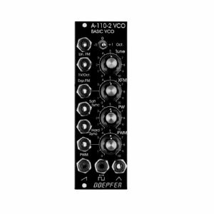
Otros clientes también compraron...
Doepfer A-110-2v Basic VCO Module (vintage edition) (synth module)
Cat: 692514 Rel: 18 Jun 18
Basic voltage-controlled oscillator for the A-100 modular system - black front panel
Notes: Module A-110-2 is a low-cost voltage-controlled oscillator. It's a slightly reduced version of the standard VCO A-110-1. Compared to the A-110-1, the A-110-2 has no sine output and the (expensive) octave rotary switch is replaced by a 3-position toggle switch. In return, the A-110-2 is equipped with an additional linear FM input and a soft sync input. A jumper is used to select the range of the tune control between about 1/2 octave and about 4 octaves. The width of the module is only 8 HP compared to the 10 HP of the A-110-1.
All other features are essentially the same as for the A-110-1.
Explanation of the jumpers and trimming potentiometers:
- JP2: CV connection to A-100 bus
- JP3: range of Tune control (installed = about 4 octaves, not installed = about 1/2 octave)
- JP4: AC/DC coupling of the linear FM input (installed = DC coupling, not installed = AC coupling)
- P5: 1V/Oct scale
- P6: frequency offset
- P7: high-end trim
- P8: adjustment +1 Oct. range switch
- P9: adjustment -1 Oct. range switch
- P10: temperature VCO heater
The core of the A-110-2 is - like the A-110-1 - a sawtooth oscillator (in contrast to the A-111-1, which is based on a triangle oscillator). The other waveforms are derived from the sawtooth by waveform converters. As the sawtooth reset (i.e. the back-to-zero slope) is not infinitely fast but takes a little bit of time the triangle is not perfect! At the bottom of the waveform it has a small glitch or notch that is caused by the sawtooth reset and cannot be eliminated by the waveform converter. If a perfect triangle is required, the A-111-1 is recommended.
The sawtooth output of the A-110-21 has a falling (or negative) slope. The front panel shows erroneously a rising (or positive) slope. This has no influence on the sound but becomes important when the module is used as an LFO or is mixed with the sawtooth output of another VCO.
The control voltage applied to the socket 1V/Oct is added to the control voltage coming from the bus (interruptible by removing the jumper JP2). Connecting a cable to the socket 1V/Oct does not interrupt the bus CV connection!
… Read moreAll other features are essentially the same as for the A-110-1.
Explanation of the jumpers and trimming potentiometers:
- JP2: CV connection to A-100 bus
- JP3: range of Tune control (installed = about 4 octaves, not installed = about 1/2 octave)
- JP4: AC/DC coupling of the linear FM input (installed = DC coupling, not installed = AC coupling)
- P5: 1V/Oct scale
- P6: frequency offset
- P7: high-end trim
- P8: adjustment +1 Oct. range switch
- P9: adjustment -1 Oct. range switch
- P10: temperature VCO heater
The core of the A-110-2 is - like the A-110-1 - a sawtooth oscillator (in contrast to the A-111-1, which is based on a triangle oscillator). The other waveforms are derived from the sawtooth by waveform converters. As the sawtooth reset (i.e. the back-to-zero slope) is not infinitely fast but takes a little bit of time the triangle is not perfect! At the bottom of the waveform it has a small glitch or notch that is caused by the sawtooth reset and cannot be eliminated by the waveform converter. If a perfect triangle is required, the A-111-1 is recommended.
The sawtooth output of the A-110-21 has a falling (or negative) slope. The front panel shows erroneously a rising (or positive) slope. This has no influence on the sound but becomes important when the module is used as an LFO or is mixed with the sawtooth output of another VCO.
The control voltage applied to the socket 1V/Oct is added to the control voltage coming from the bus (interruptible by removing the jumper JP2). Connecting a cable to the socket 1V/Oct does not interrupt the bus CV connection!
out of stock $130.64
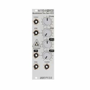
Otros clientes también compraron...
Doepfer A-110-4 Quadrature Thru Zero VCO Module (silver) (oscillator synth module)
Cat: 692515 Rel: 18 Jun 18
Thru-zero quadrature VCO with Sine/Cosine core - standard edition
Notes: This analogue VCO is well versed in the art of deep and beautiful thru-zero frequency modulation, allowing the frequency to stop when CVs with 0V are applied, and even to go backwards when modulated with negative CVs.
The term "quadrature" refers to simultaneously available sine and cosine waves at individual outputs. The VCO is sine based i.e. no waveshaping is used to derive the sine; for that reason, the sound is really clear and shows a minimum of distortion and overtones.
The module has two control sections:
The exponential section consists of the XTune control, the 1V/Oct input and the XFM input with the corresponding attenuator XFM.
The exponential control voltage is the sum of these three voltages. The linear section consists of the LTune control and the LFM input with the corresponding attenuator LFM. The linear control voltage is the sum of these two voltages.
The main advantage of the A-110-4 compared to other Thru Zero VCOs is that the design uses a sine/cosine core. The sine/cosine waves are not derived from other waveforms (e.g. sawtooth or triangle) by means of waveshaping. Rather the sine and cosine waves are the core of the VCO which results in very pure waves with a minimum of distortion and overtones.
With it's both control possibilities, linear and exponential, as well as it's thru-zero ability, the VCO is perfectly suited for all types of FM applications.
… Read moreThe term "quadrature" refers to simultaneously available sine and cosine waves at individual outputs. The VCO is sine based i.e. no waveshaping is used to derive the sine; for that reason, the sound is really clear and shows a minimum of distortion and overtones.
The module has two control sections:
The exponential section consists of the XTune control, the 1V/Oct input and the XFM input with the corresponding attenuator XFM.
The exponential control voltage is the sum of these three voltages. The linear section consists of the LTune control and the LFM input with the corresponding attenuator LFM. The linear control voltage is the sum of these two voltages.
The main advantage of the A-110-4 compared to other Thru Zero VCOs is that the design uses a sine/cosine core. The sine/cosine waves are not derived from other waveforms (e.g. sawtooth or triangle) by means of waveshaping. Rather the sine and cosine waves are the core of the VCO which results in very pure waves with a minimum of distortion and overtones.
With it's both control possibilities, linear and exponential, as well as it's thru-zero ability, the VCO is perfectly suited for all types of FM applications.
out of stock $124.11
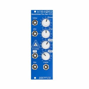
Otros clientes también compraron...
Doepfer A-110-4 Quadrature Thru-Zero Voltage Controlled Oscillator Special Edition Module (blue) (oscillator synth module)
Cat: 692516 Rel: 18 Jun 18
Thru-zero quadrature VCO with Sine/Cosine core - special edition
Notes: This analogue VCO is well versed in the art of deep and beautiful thru-zero frequency modulation, allowing the frequency to stop when CVs with 0V are applied, and even to go backwards when modulated with negative CVs.
The term "quadrature" refers to simultaneously available sine and cosine waves at individual outputs. The VCO is sine based i.e. no waveshaping is used to derive the sine; for that reason, the sound is really clear and shows a minimum of distortion and overtones.
The module has two control sections:
The exponential section consists of the XTune control, the 1V/Oct input and the XFM input with the corresponding attenuator XFM.
The exponential control voltage is the sum of these three voltages. The linear section consists of the LTune control and the LFM input with the corresponding attenuator LFM. The linear control voltage is the sum of these two voltages.
The main advantage of the A-110-4 compared to other Thru Zero VCOs is that the design uses a sine/cosine core. The sine/cosine waves are not derived from other waveforms (e.g. sawtooth or triangle) by means of waveshaping. Rather the sine and cosine waves are the core of the VCO which results in very pure waves with a minimum of distortion and overtones.
With it's both control possibilities, linear and exponential, as well as it's thru-zero ability, the VCO is perfectly suited for all types of FM applications.
… Read moreThe term "quadrature" refers to simultaneously available sine and cosine waves at individual outputs. The VCO is sine based i.e. no waveshaping is used to derive the sine; for that reason, the sound is really clear and shows a minimum of distortion and overtones.
The module has two control sections:
The exponential section consists of the XTune control, the 1V/Oct input and the XFM input with the corresponding attenuator XFM.
The exponential control voltage is the sum of these three voltages. The linear section consists of the LTune control and the LFM input with the corresponding attenuator LFM. The linear control voltage is the sum of these two voltages.
The main advantage of the A-110-4 compared to other Thru Zero VCOs is that the design uses a sine/cosine core. The sine/cosine waves are not derived from other waveforms (e.g. sawtooth or triangle) by means of waveshaping. Rather the sine and cosine waves are the core of the VCO which results in very pure waves with a minimum of distortion and overtones.
With it's both control possibilities, linear and exponential, as well as it's thru-zero ability, the VCO is perfectly suited for all types of FM applications.
out of stock $142.72
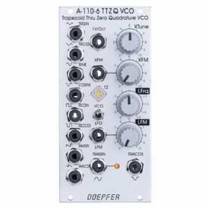
Otros clientes también compraron...
Doepfer A-110-6 Trapezoid Thru Zero Quadrature VCO Module (oscillator synth module)
Cat: 671595 Rel: 29 Nov 17
Trapezoid thru-zero quadrature VCO module - 12HP
Notes: A-110-6 is a Trapezoid Thru Zero Quadrature VCO. The module is based on an idea by Donald Tillman from 2003 but has been revised for the use of modern electronic circuits (no OTAs/CA3280). Because of its unique trapezoid core it's totally different compared to other VCOs. But the trapezoid core is not the only specialty: it is also a quadrature VCO and features linear thru zero frequency modulation.
The term "quadrature" means in this connection that the oscillator outputs two trapezoid waves with 90 degrees phase shift. The same as sine and cosine of a standard quadrature oscillator like the A-110-4 or A-143-9. These waveforms are called TRASIN (trapezoid sine) and TRACOS (trapezoid cosine).
The term "Thru-Zero" means that even "negative" frequencies are generated. But this a bit a misleading term as negative frequencies do not really exist. "Negative" means in this connection simply that the TRASIN/TRACOS waves will stop when the linear control voltage reaches 0V and continue with the opposite directions as the linear control voltage becomes negative and vice versa.
The module has two control sections: linear and a exponential. The exponential section consists of the XTune control, the 1V/Oct input and the XFM input with the corresponding attenuator XFM. The exponential control voltage is the sum of these three voltages. The linear section consists of the LFrq control and the LFM input with the corresponding attenuator LFM. The linear control voltage is the sum of these two voltages. A dual colour LED is used to display the polarity of the linear control voltage. The pitch of all outputs is determined by the control voltages of both sections. The linear section is used to control the pitch in a linear manner. When the LFrq control (LFrq means Linear Frequency Control) is fully CW the module works like a normal VCO and the LED lights red. The pitch is then controlled by the exponential section with the manual Tune control XTune and the exponential frequency control inputs 1V/Oct and XFM. 1V/Oct is used to control the pitch by a 1V/Oct CV source (e.g. sequencer or Midi/USB-to-CV interface). XFM is used to apply an exponential frequency modulation with adjustable depth (e.g. from an LFO or another VCO). As the LFrq control is turned counter-clockwise starting from the fully CW position the frequency is lowered in a linear manner until the TRASIN/TRACOS waves (nearly) stop at the centre position of LFrq (provided that no LFM signal is present). As the LFrq control is moved from the centre towards the CCW position the waves start again but into reverse direction and the LED turns yellow. When the fully CCW position of LFrq is reached the module works again like a normal VCO. But much more exciting is the usage of the LFM input to modify the linear control voltage by an external control voltage (typically another VCO). Linear modulation by another oscillator using the thru zero feature in combination with the trapezoid waveforms generates audio spectra than cannot be obtained from any other oscillator without the thru zero function. The reason is that a "normal" VCO will simply stop as the linear control voltage becomes zero or negative. But a thru zero VCO will start again with "negative" frequencies as the linear control voltage becomes negative.
Other waveforms like triangle, sawtooth, rectangle and sine can be obtained from the TRASIN/TRACOS signals (triangle e.g. simply by subtracting TRISIN and TRICOS, SAWSIN and SAWCOS by switching the other waveforms). All five waveforms are available as quadrature pairs (i.e. with 90 degrees phase shift):
- Trapezoid (TRASIN + TRACOS)
- Triangle (TRISIN + TRICOS)
- Sinus (SIN + COS)
- Rectangle (RECSIN + RECCOS)
- Sawtooth (SAWSIN + SAWCOS)
By means of a toggle switch the frequency range can be selected between VCO (audio range) and LFO. In LFO range the frequencies are about 1/100 compared to VCO mode.
A dual-colour LED display the polarity of the linear control section. Another dual-colour LED shows the signal TRASIN which is helpful in LFO mode.
Technical note regarding linear FM: The LFM CV input is DC coupled. If the input is used for linear FM in audio range and the signal applied to this input has a DC offset it will cause a small pitch shift that depends upon the value of the DC voltage. Especially when a VCA is used to change dynamically the level of the modulation signal this may generate a pitch shift caused by the control voltage feedthrough of the VCA. The control voltage feedthrough adds a DC voltage at the output which depends upon the control voltage of the VCA. For this application VCAs with a very low CV feed though should be used or the signal output of the VCA should be AC coupled to the LFM input of the A-110-6 (e.g. by inserting a capacitor).
Dimensions
12 HP
61 mm deep
Current draw
80 mA +12V
70 mA -12V
… Read moreThe term "quadrature" means in this connection that the oscillator outputs two trapezoid waves with 90 degrees phase shift. The same as sine and cosine of a standard quadrature oscillator like the A-110-4 or A-143-9. These waveforms are called TRASIN (trapezoid sine) and TRACOS (trapezoid cosine).
The term "Thru-Zero" means that even "negative" frequencies are generated. But this a bit a misleading term as negative frequencies do not really exist. "Negative" means in this connection simply that the TRASIN/TRACOS waves will stop when the linear control voltage reaches 0V and continue with the opposite directions as the linear control voltage becomes negative and vice versa.
The module has two control sections: linear and a exponential. The exponential section consists of the XTune control, the 1V/Oct input and the XFM input with the corresponding attenuator XFM. The exponential control voltage is the sum of these three voltages. The linear section consists of the LFrq control and the LFM input with the corresponding attenuator LFM. The linear control voltage is the sum of these two voltages. A dual colour LED is used to display the polarity of the linear control voltage. The pitch of all outputs is determined by the control voltages of both sections. The linear section is used to control the pitch in a linear manner. When the LFrq control (LFrq means Linear Frequency Control) is fully CW the module works like a normal VCO and the LED lights red. The pitch is then controlled by the exponential section with the manual Tune control XTune and the exponential frequency control inputs 1V/Oct and XFM. 1V/Oct is used to control the pitch by a 1V/Oct CV source (e.g. sequencer or Midi/USB-to-CV interface). XFM is used to apply an exponential frequency modulation with adjustable depth (e.g. from an LFO or another VCO). As the LFrq control is turned counter-clockwise starting from the fully CW position the frequency is lowered in a linear manner until the TRASIN/TRACOS waves (nearly) stop at the centre position of LFrq (provided that no LFM signal is present). As the LFrq control is moved from the centre towards the CCW position the waves start again but into reverse direction and the LED turns yellow. When the fully CCW position of LFrq is reached the module works again like a normal VCO. But much more exciting is the usage of the LFM input to modify the linear control voltage by an external control voltage (typically another VCO). Linear modulation by another oscillator using the thru zero feature in combination with the trapezoid waveforms generates audio spectra than cannot be obtained from any other oscillator without the thru zero function. The reason is that a "normal" VCO will simply stop as the linear control voltage becomes zero or negative. But a thru zero VCO will start again with "negative" frequencies as the linear control voltage becomes negative.
Other waveforms like triangle, sawtooth, rectangle and sine can be obtained from the TRASIN/TRACOS signals (triangle e.g. simply by subtracting TRISIN and TRICOS, SAWSIN and SAWCOS by switching the other waveforms). All five waveforms are available as quadrature pairs (i.e. with 90 degrees phase shift):
- Trapezoid (TRASIN + TRACOS)
- Triangle (TRISIN + TRICOS)
- Sinus (SIN + COS)
- Rectangle (RECSIN + RECCOS)
- Sawtooth (SAWSIN + SAWCOS)
By means of a toggle switch the frequency range can be selected between VCO (audio range) and LFO. In LFO range the frequencies are about 1/100 compared to VCO mode.
A dual-colour LED display the polarity of the linear control section. Another dual-colour LED shows the signal TRASIN which is helpful in LFO mode.
Technical note regarding linear FM: The LFM CV input is DC coupled. If the input is used for linear FM in audio range and the signal applied to this input has a DC offset it will cause a small pitch shift that depends upon the value of the DC voltage. Especially when a VCA is used to change dynamically the level of the modulation signal this may generate a pitch shift caused by the control voltage feedthrough of the VCA. The control voltage feedthrough adds a DC voltage at the output which depends upon the control voltage of the VCA. For this application VCAs with a very low CV feed though should be used or the signal output of the VCA should be AC coupled to the LFM input of the A-110-6 (e.g. by inserting a capacitor).
Dimensions
12 HP
61 mm deep
Current draw
80 mA +12V
70 mA -12V
out of stock $230.55

Otros clientes también compraron...
Doepfer A-111-2 VCO High End Voltage Controlled Oscillator II Module (silver) (oscillator/LFO module)
Cat: 692521 Rel: 19 Jun 18
Voltage controlled oscillator module - 14HP
Notes: The successor of the good old A-111 High End oscillator is an utterly precise analogue VCO/LFO with an extremely big frequency range, immaculate tracking over at least ten octaves and nearly perfect waveforms. With linear and exponential FM, pulse width modulation, two simultaneous types of sync and attenuators on all CV inputs, the module is really well-appointed.
Not less than four frequency controls make tuning an ease:
- Switch for LFO or VCO range
- Octave rotary switch with six positions
- Fine tuning control (approximately one octave range)
- Coarse tune control (approximately one semitone range)
The oscillator has a frequency range of at least fifteen octaves (0.0001 - 40Hz in LFO mode, 0.5Hz - 20kHz in VCO mode) and has perfect Volt per octave tracking over at least ten octaves, typically in the range of 20Hz to 20kHz. Frequencies below 25Hz are visualized with a two-colour LED.
An 1V/octave input without attenuator is expanded by two scaleable FM inputs, one for linear and one for exponential frequency modulation. Using a jumper, you can decide whether the module obtains pitch CV via the internal bus.
The VCO has a triangle core from which sawtooth, pulse and sine are derived. The wave forms are almost perfect and sans glitches.
The pulse width can be set with a control from 0 to 100% and of course it can be modulated.
The A-111-2 features not only one but two inputs for oscillator synchronisation - one for hard and one for soft sync, which both differ in sound with the hard sync being more aggressive and richer in harmonics.
… Read moreNot less than four frequency controls make tuning an ease:
- Switch for LFO or VCO range
- Octave rotary switch with six positions
- Fine tuning control (approximately one octave range)
- Coarse tune control (approximately one semitone range)
The oscillator has a frequency range of at least fifteen octaves (0.0001 - 40Hz in LFO mode, 0.5Hz - 20kHz in VCO mode) and has perfect Volt per octave tracking over at least ten octaves, typically in the range of 20Hz to 20kHz. Frequencies below 25Hz are visualized with a two-colour LED.
An 1V/octave input without attenuator is expanded by two scaleable FM inputs, one for linear and one for exponential frequency modulation. Using a jumper, you can decide whether the module obtains pitch CV via the internal bus.
The VCO has a triangle core from which sawtooth, pulse and sine are derived. The wave forms are almost perfect and sans glitches.
The pulse width can be set with a control from 0 to 100% and of course it can be modulated.
The A-111-2 features not only one but two inputs for oscillator synchronisation - one for hard and one for soft sync, which both differ in sound with the hard sync being more aggressive and richer in harmonics.
out of stock $226.16
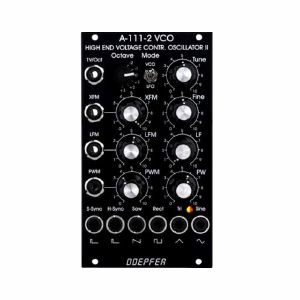
Otros clientes también compraron...
Doepfer A-111-2v High End Voltage Controlled Oscillator II Vintage Edition Module (black) (LFO/oscillator module)
Cat: 692522 Rel: 19 Jun 18
High end voltage controlled oscillator module - 14HP
Notes: The successor of the good old A-111 High End oscillator is an utterly precise analogue VCO/LFO with an extremely big frequency range, immaculate tracking over at least ten octaves and nearly perfect waveforms. With linear and exponential FM, pulse width modulation, two simultaneous types of sync and attenuators on all CV inputs, the module is really well-appointed.
Here are the most important features of the module:
triangle core (i.e. all other waveforms are derived from the triangle by waveshapers)
fully analog design
min. 15 octaves pitch range (typ. 0.5Hz - 20kHz in VCO mode / 0.001Hz - 40Hz in LFO mode)
perfect 1V/octave tracking over min. 10 octaves, typ. 20Hz - 20kHz (control LF has to be fully CW for perfect 1V/octave tracking)
exponential frequency controls and inputs:
Tune: range can be selected by means of a jumper, about +/- 1 octave (jumper JP6 not installed) or about +/- 3 octaves (jumper JP6 installed)
Fine: about +/- 1 semitone range
Octave: range switch with 6 positions for 6 octaves
1V/octave CV input
XFM input with attenuator
access to internal bus CV (via jumper, optional, please remove the bus jumper if this feature is not used to avoid unwanted frequency modulation as then the unused CV line of the bus works as a kind of antenna)
linear frequency controls and inputs:
LF (manual linear frequency control: fully CW = standard setting for usual VCO applications, fully CCW: close to 0Hz frequency) works also as a kind of range control for the exponential section but for standard VCO applications with 1V/octave control voltage the LF control should be fully CW !
LFM input with attenuator, DC coupled
Pulsewidth controls and inputs (for rectangle output):
PW (manual pulsewidth control from 0%/output = fixed at "low" state up to 100% / output fixed at "high" state)
PWM input with attenuator
Hard Sync input (CEM3340 hard sync type)
Soft Sync input
Waveform outputs:
Sawtooth, output level ~ 10Vpp (voltage range ~ 0 ... +10V)
Rectangle (controlled from pulsewidth section), output level ~ 10Vpp (voltage range ~ 0 ... +10V)
Triangle (output level ~ 10Vpp, voltage range ~ -5V ... +5V)
Sine (output level ~ 10Vpp, voltage range ~ -5V ... +5V)
Range switch to select VCO/VCLFO mode, frequency relation between VCO mode and LFO mode about 500 : 1
dual color LED display (to display low frequencies below ~ 25 Hz)
Nearly "perfect" waveforms
high end triangle to sine converter with excellent sine waveshape (thank's to Tim Stinchcombe who recommended this circuit)
the micro precision VCO A-111-3 uses the same VCO core as the A-111-2, but has less inputs, outputs and controls
… Read moreHere are the most important features of the module:
triangle core (i.e. all other waveforms are derived from the triangle by waveshapers)
fully analog design
min. 15 octaves pitch range (typ. 0.5Hz - 20kHz in VCO mode / 0.001Hz - 40Hz in LFO mode)
perfect 1V/octave tracking over min. 10 octaves, typ. 20Hz - 20kHz (control LF has to be fully CW for perfect 1V/octave tracking)
exponential frequency controls and inputs:
Tune: range can be selected by means of a jumper, about +/- 1 octave (jumper JP6 not installed) or about +/- 3 octaves (jumper JP6 installed)
Fine: about +/- 1 semitone range
Octave: range switch with 6 positions for 6 octaves
1V/octave CV input
XFM input with attenuator
access to internal bus CV (via jumper, optional, please remove the bus jumper if this feature is not used to avoid unwanted frequency modulation as then the unused CV line of the bus works as a kind of antenna)
linear frequency controls and inputs:
LF (manual linear frequency control: fully CW = standard setting for usual VCO applications, fully CCW: close to 0Hz frequency) works also as a kind of range control for the exponential section but for standard VCO applications with 1V/octave control voltage the LF control should be fully CW !
LFM input with attenuator, DC coupled
Pulsewidth controls and inputs (for rectangle output):
PW (manual pulsewidth control from 0%/output = fixed at "low" state up to 100% / output fixed at "high" state)
PWM input with attenuator
Hard Sync input (CEM3340 hard sync type)
Soft Sync input
Waveform outputs:
Sawtooth, output level ~ 10Vpp (voltage range ~ 0 ... +10V)
Rectangle (controlled from pulsewidth section), output level ~ 10Vpp (voltage range ~ 0 ... +10V)
Triangle (output level ~ 10Vpp, voltage range ~ -5V ... +5V)
Sine (output level ~ 10Vpp, voltage range ~ -5V ... +5V)
Range switch to select VCO/VCLFO mode, frequency relation between VCO mode and LFO mode about 500 : 1
dual color LED display (to display low frequencies below ~ 25 Hz)
Nearly "perfect" waveforms
high end triangle to sine converter with excellent sine waveshape (thank's to Tim Stinchcombe who recommended this circuit)
the micro precision VCO A-111-3 uses the same VCO core as the A-111-2, but has less inputs, outputs and controls
out of stock $239.76
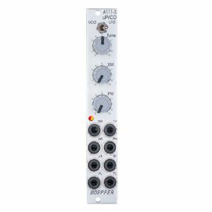
Otros clientes también compraron...
Doepfer A-111-3 Micro Precision VCO Slim Line Series Module (silver) (oscillator/LFO synth module)
Cat: 671591 Rel: 29 Nov 17
Analog VCO/LFO module with wide frequency range - 4HP
Notes: The Micro Precision VCO is a space-saving and utterly precise analog VCO/LFO with a extremely wide frequency range, immaculate tracking over at least ten octaves and nearly perfect waveforms.
Basically, it's the same circuitry like the High-End VCO A-111-2 but with reduced functions and controls. It is suitable as a modulator for exact linear FM and much more.
The A-111-3 has two elements for setting the frequency: A switch selecting between LFO and VCO mode as well as a tune control with a jumper-selectable range:
- Jumper position 1: 16Hz to 20 kHz
- Jumper position 2: 16Hz to 70Hz
- Without jumper: 16Hz to 22Hz
The XM potentiometer can be used as a fine tune control as long as nothing is patched to the XM socket.
The oscillator has a frequency range of at least fifteen osctaves (0.0001 - 40 Hz in LFO mode; 0.5 Hz to 20 kHz in VCO mode) and offers perfect 1 V per octave tracking over ten octaves minimum, typically in the range of 20 Hz to 20 kHz. Frequencies below 25 Hz are visualized with a two-colour LED.
The 1V per octave input is accompanied by two FM inputs, one for linear and one for exponential frequency modulation. A jumper determines whether the module obtains pitch CV via the internal bus.
The VCO has a triangle core from which sawtooth, pulse and triangle are derived. The wave forms are almost perfect and sans glitches.
The pulse width can be set with a control from 0 to 100% and of course it can be modulated.
There is one input for oscillator synchronisation and its type, either hard or soft sync, is jumper-selected. Both types differ in sound with the hard sync being more aggressive and richer in harmonics.
… Read moreBasically, it's the same circuitry like the High-End VCO A-111-2 but with reduced functions and controls. It is suitable as a modulator for exact linear FM and much more.
The A-111-3 has two elements for setting the frequency: A switch selecting between LFO and VCO mode as well as a tune control with a jumper-selectable range:
- Jumper position 1: 16Hz to 20 kHz
- Jumper position 2: 16Hz to 70Hz
- Without jumper: 16Hz to 22Hz
The XM potentiometer can be used as a fine tune control as long as nothing is patched to the XM socket.
The oscillator has a frequency range of at least fifteen osctaves (0.0001 - 40 Hz in LFO mode; 0.5 Hz to 20 kHz in VCO mode) and offers perfect 1 V per octave tracking over ten octaves minimum, typically in the range of 20 Hz to 20 kHz. Frequencies below 25 Hz are visualized with a two-colour LED.
The 1V per octave input is accompanied by two FM inputs, one for linear and one for exponential frequency modulation. A jumper determines whether the module obtains pitch CV via the internal bus.
The VCO has a triangle core from which sawtooth, pulse and triangle are derived. The wave forms are almost perfect and sans glitches.
The pulse width can be set with a control from 0 to 100% and of course it can be modulated.
There is one input for oscillator synchronisation and its type, either hard or soft sync, is jumper-selected. Both types differ in sound with the hard sync being more aggressive and richer in harmonics.
out of stock $162.49
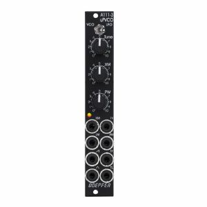
Otros clientes también compraron...
Doepfer A-111-3v Micro Precision VCO & VCLFO Module (vintage edition) (LFO/oscillator synth module)
Cat: 692518 Rel: 18 Jun 18
Analog VCO/LFO module with wide frequency range - 4HP
Notes: The Micro Precision VCO is a space-saving and utterly precise analog VCO/LFO with a extremely wide frequency range, immaculate tracking over at least ten octaves and nearly perfect waveforms.
Basically, it's the same circuitry like the High-End VCO A-111-2 but with reduced functions and controls. It is suitable as a modulator for exact linear FM and much more.
The A-111-3 has two elements for setting the frequency: A switch selecting between LFO and VCO mode as well as a tune control with a jumper-selectable range:
- Jumper position 1: 16Hz to 20 kHz
- Jumper position 2: 16Hz to 70Hz
- Without jumper: 16Hz to 22Hz
The XM potentiometer can be used as a fine tune control as long as nothing is patched to the XM socket.
The oscillator has a frequency range of at least fifteen osctaves (0.0001 - 40 Hz in LFO mode; 0.5 Hz to 20 kHz in VCO mode) and offers perfect 1 V per octave tracking over ten octaves minimum, typically in the range of 20 Hz to 20 kHz. Frequencies below 25 Hz are visualized with a two-colour LED.
The 1V per octave input is accompanied by two FM inputs, one for linear and one for exponential frequency modulation. A jumper determines whether the module obtains pitch CV via the internal bus.
The VCO has a triangle core from which sawtooth, pulse and triangle are derived. The wave forms are almost perfect and sans glitches.
The pulse width can be set with a control from 0 to 100% and of course it can be modulated.
There is one input for oscillator synchronisation and its type, either hard or soft sync, is jumper-selected. Both types differ in sound with the hard sync being more aggressive and richer in harmonics.
… Read moreBasically, it's the same circuitry like the High-End VCO A-111-2 but with reduced functions and controls. It is suitable as a modulator for exact linear FM and much more.
The A-111-3 has two elements for setting the frequency: A switch selecting between LFO and VCO mode as well as a tune control with a jumper-selectable range:
- Jumper position 1: 16Hz to 20 kHz
- Jumper position 2: 16Hz to 70Hz
- Without jumper: 16Hz to 22Hz
The XM potentiometer can be used as a fine tune control as long as nothing is patched to the XM socket.
The oscillator has a frequency range of at least fifteen osctaves (0.0001 - 40 Hz in LFO mode; 0.5 Hz to 20 kHz in VCO mode) and offers perfect 1 V per octave tracking over ten octaves minimum, typically in the range of 20 Hz to 20 kHz. Frequencies below 25 Hz are visualized with a two-colour LED.
The 1V per octave input is accompanied by two FM inputs, one for linear and one for exponential frequency modulation. A jumper determines whether the module obtains pitch CV via the internal bus.
The VCO has a triangle core from which sawtooth, pulse and triangle are derived. The wave forms are almost perfect and sans glitches.
The pulse width can be set with a control from 0 to 100% and of course it can be modulated.
There is one input for oscillator synchronisation and its type, either hard or soft sync, is jumper-selected. Both types differ in sound with the hard sync being more aggressive and richer in harmonics.
out of stock $169.07
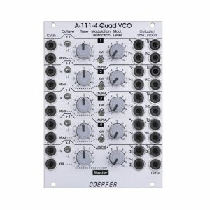
Otros clientes también compraron...
Doepfer A-111-4 Quad Precision VCO Module (silver) (oscillator synth module)
Cat: 671550 Rel: 29 Nov 17
Quad precision voltage contolled oscillator module - 18HP
Notes: A-111-4 contains four precision VCOs and has individual controls, inputs and outputs for each VCO available as well as a common control and output unit. After all the A-111-4 is very similar to four A-111-3 without LFO mode but built in output mixers for the three waveforms, and a master unit for all four VCOs.
Controls, inputs and outputs for each of the four VCOs:
- 1V/Octave CV input
- Octave switch (+1 / 0 / -1 octave)
- Tune control (range internally adjustable by jumpers: ~ 2 semitones / ~ 1 octave / ~ 4 octaves)
- Modulation CV input
- Modulation destination:
- Upper position: exponential frequency modulation (XM)lower position: linear frequency modulation (LM) or pulsewidth modulation of the rectangle (PM), selectable via internal jumper
- Frequency Modulation (FM) or Pulsewidth Modulation of the rectangle (PWM)
- Modulation intensity
- Triangle output
- Sawtooth output
- Rectangle output (about 50% without external PWM)
- Sync input (hard or soft sync internally selectable via jumper, CEM3340 hard sync type)
- Min. 10 octaves range (with appropriate external CV)
- CEM3340 based VCO (triangle core)
- Each VCO has it's own separate internal +/- power supply for each for best stability and the prevention of unwanted synchronisation of the VCOs
Controls, inputs and outputs of the master section:
- 1V/Octave CV input
- Octave switch (+1 / 0 / -1 octave)
- Tune control (range internally adjustable by jumpers: 2 semitones / 1 octave / 4 octaves)
- Frequency Modulation CV input (FM)
- FM intensity
- Triangle sum output
- Sawtooth sum output
- Rectangle sum output
- As soon as the single waveform output of a VCO is patched this waveform of the VCO in question is removed from the sum (this function can be turned off for each single output socket by means of solder bridges on the pc board, i.e. the sum contains then all signals independent of the patching of the single output)
- CV output (outputs the sum CV that is used to control all four VCOs)
- Bus CV (selectable via jumper)
Typical applications:
- Fat sounding monophonic VCO with the possibility to adjust any intervals
- Paraphonic patches in combination with the polyphonic CV interface A-190-5 (all four VCOs processed by one VCF/VCA)
- Full polyphonic patches in combination with the polyphonic CV interface A-190-5 and four complete VCF/VCA sections
- Complex VCO patches with up to four VCOs by means of the frequency modulation features (exponential an linear) and the sync functions
… Read moreControls, inputs and outputs for each of the four VCOs:
- 1V/Octave CV input
- Octave switch (+1 / 0 / -1 octave)
- Tune control (range internally adjustable by jumpers: ~ 2 semitones / ~ 1 octave / ~ 4 octaves)
- Modulation CV input
- Modulation destination:
- Upper position: exponential frequency modulation (XM)lower position: linear frequency modulation (LM) or pulsewidth modulation of the rectangle (PM), selectable via internal jumper
- Frequency Modulation (FM) or Pulsewidth Modulation of the rectangle (PWM)
- Modulation intensity
- Triangle output
- Sawtooth output
- Rectangle output (about 50% without external PWM)
- Sync input (hard or soft sync internally selectable via jumper, CEM3340 hard sync type)
- Min. 10 octaves range (with appropriate external CV)
- CEM3340 based VCO (triangle core)
- Each VCO has it's own separate internal +/- power supply for each for best stability and the prevention of unwanted synchronisation of the VCOs
Controls, inputs and outputs of the master section:
- 1V/Octave CV input
- Octave switch (+1 / 0 / -1 octave)
- Tune control (range internally adjustable by jumpers: 2 semitones / 1 octave / 4 octaves)
- Frequency Modulation CV input (FM)
- FM intensity
- Triangle sum output
- Sawtooth sum output
- Rectangle sum output
- As soon as the single waveform output of a VCO is patched this waveform of the VCO in question is removed from the sum (this function can be turned off for each single output socket by means of solder bridges on the pc board, i.e. the sum contains then all signals independent of the patching of the single output)
- CV output (outputs the sum CV that is used to control all four VCOs)
- Bus CV (selectable via jumper)
Typical applications:
- Fat sounding monophonic VCO with the possibility to adjust any intervals
- Paraphonic patches in combination with the polyphonic CV interface A-190-5 (all four VCOs processed by one VCF/VCA)
- Full polyphonic patches in combination with the polyphonic CV interface A-190-5 and four complete VCF/VCA sections
- Complex VCO patches with up to four VCOs by means of the frequency modulation features (exponential an linear) and the sync functions
1 in stock $377.67
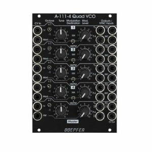
Otros clientes también compraron...
Doepfer A-111-4v Quad Precision VCO Vintage Edition Module (black) (oscillator/quad synth module)
Cat: 734878 Rel: 09 Jul 19
Quad precision VCO - 18HP
Notes: A-111-4 contains four precision VCOs and has individual controls, inputs and outputs for each VCO available as well as a common control and output unit. After all the A-111-4 is very similar to four A-111-3 without LFO mode but built in output mixers for the three waveforms, and a master unit for all four VCOs.
Controls, inputs and outputs for each of the four VCOs:
- 1V/Octave CV input
- Octave switch (+1 / 0 / -1 octave)
- Tune control (range internally adjustable by jumpers: ~ 2 semitones / ~ 1 octave / ~ 4 octaves)
- Modulation CV input
- Modulation destination: Upper position: exponential frequency modulation (XM) / Lower position: linear frequency modulation (LM) or pulsewidth modulation of the rectangle (PM), selectable via internal jumper
- Frequency Modulation (FM) or Pulsewidth Modulation of the rectangle (PWM)
- Modulation intensity
- Triangle output
- Sawtooth output
- Rectangle output (about 50% without external PWM)
- Sync input (hard or soft sync internally selectable via jumper, CEM3340 hard sync type)
- CEM3340 based VCO (triangle core)
- Each VCO has it's own separate internal +/- power supply for each for best stability and the prevention of unwanted synchronisation of the VCOs
Controls, inputs and outputs of the master section:
- 1V/Octave CV input
- Octave switch (+1 / 0 / -1 octave)
- Tune control (range internally adjustable by jumpers: 2 semitones / 1 octave / 4 octaves)
- Frequency Modulation CV input (FM)
- FM intensity
- Triangle sum output
- Sawtooth sum output
- Rectangle sum output
- As soon as the single waveform output of a VCO is patched this waveform of the VCO in question is removed from the sum (this function can be turned off for each single output socket by means of solder bridges on the pc board, i.e. the sum contains then all signals independent of the patching of the single output)
- CV output (outputs the sum CV that is used to control all four VCOs)
- Bus CV (via jumper, optional, please remove the bus jumper if this feature is not used to avoid unwanted frequency modulation as then the unused CV line of the bus works as a kind of antenna)
Typical applications:
- Fat sounding monophonic VCO with the possibility to adjust any intervals
- Paraphonic patches in combination with the polyphonic CV interface A-190-5 (all four VCOs processed by one VCF/VCA)
- Full polyphonic patches in combination with the polyphonic CV interface A-190-5 and four complete VCF/VCA sections
- Complex VCO patches with up to four VCOs by means of the frequency modulation features (exponential an linear) and the sync functions
… Read moreControls, inputs and outputs for each of the four VCOs:
- 1V/Octave CV input
- Octave switch (+1 / 0 / -1 octave)
- Tune control (range internally adjustable by jumpers: ~ 2 semitones / ~ 1 octave / ~ 4 octaves)
- Modulation CV input
- Modulation destination: Upper position: exponential frequency modulation (XM) / Lower position: linear frequency modulation (LM) or pulsewidth modulation of the rectangle (PM), selectable via internal jumper
- Frequency Modulation (FM) or Pulsewidth Modulation of the rectangle (PWM)
- Modulation intensity
- Triangle output
- Sawtooth output
- Rectangle output (about 50% without external PWM)
- Sync input (hard or soft sync internally selectable via jumper, CEM3340 hard sync type)
- CEM3340 based VCO (triangle core)
- Each VCO has it's own separate internal +/- power supply for each for best stability and the prevention of unwanted synchronisation of the VCOs
Controls, inputs and outputs of the master section:
- 1V/Octave CV input
- Octave switch (+1 / 0 / -1 octave)
- Tune control (range internally adjustable by jumpers: 2 semitones / 1 octave / 4 octaves)
- Frequency Modulation CV input (FM)
- FM intensity
- Triangle sum output
- Sawtooth sum output
- Rectangle sum output
- As soon as the single waveform output of a VCO is patched this waveform of the VCO in question is removed from the sum (this function can be turned off for each single output socket by means of solder bridges on the pc board, i.e. the sum contains then all signals independent of the patching of the single output)
- CV output (outputs the sum CV that is used to control all four VCOs)
- Bus CV (via jumper, optional, please remove the bus jumper if this feature is not used to avoid unwanted frequency modulation as then the unused CV line of the bus works as a kind of antenna)
Typical applications:
- Fat sounding monophonic VCO with the possibility to adjust any intervals
- Paraphonic patches in combination with the polyphonic CV interface A-190-5 (all four VCOs processed by one VCF/VCA)
- Full polyphonic patches in combination with the polyphonic CV interface A-190-5 and four complete VCF/VCA sections
- Complex VCO patches with up to four VCOs by means of the frequency modulation features (exponential an linear) and the sync functions
out of stock $461.11
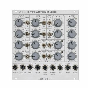
Otros clientes también compraron...
Doepfer A-111-5 Mini Synthesiser Voice Module (silver) (envelope generator/filter/LFO/oscillator/VCA/synth voice synth module)
Cat: 785445 Rel: 10 Sep 20
A complete monophonic synthesiser module (modular version of Dark Energy).
Notes: A fully modular, Eurorack-format version of the excellent Dark Energy synth, the A-111-5 offers VCO, VCF, LFOs, VCA and envelope generator in a compact format. Brilliant value for a starter system.
Supplier's Notes:
Module A-111-5 is a complete monophonic synthesizer module that includes these components (modular version of Dark Energy):
VCO
Manual tune control (with an internal jumper the range can be set to ~ +/-1 half an octave or ~ +/-2.5 octaves)
Range switch -1 / 0 / +1 octave
Frequency range about 10Hz ... 12kHz - FM (frequency modulation) control with modulation source switch (LFO1 / off / ADSR)
Manual pulsewidth control for rectangle waveform
PWM control with modulation source switch (LFO2 / off / ADSR)
Waveform switch (sawtooth / off / triangle)
The sum of the waveform chosen by this switch and the rectangle is fed into the VCF (to turn the rectangle off the PW control has to be set fully CCW)
External CV input for VCO frequency (1V/octave)
External CV input for external PWM of the rectangle - internal CV input for frequency (1V/octave) connected to the A-100 bus via jumper, the jumper can be used to interrupt this internal connection if not wanted
VCF
24 dB low pass
~ 12 octaves frequency range
Manual frequency control
Tracking switch half - off - full (internally connected to the external frequency CV input of the VCO, i.e. the VCF tracks to the VCO if the switch is set to "half" or "full" position)
XM: exponential FM (frequency modulation) control with modulation source switch (LFO2 / off / ADSR)
LM: linear FM (frequency modulation) control to modulate the VCF by the triangle of the VCO in a linear (!) manner
Manual resonance control (up to self oscillation)
External audio input (this signal is added to the VCO signal)
External CV input for filter frequency - 1V/octave tracking for usage of the VCF as a sine wave oscillator (not as precise as the VCO but much better than most of the other filters)
VCA
Manual amplitude control
AM (amplitude modulation) control with modulation source switch (LFO1 / off / ADSR)
External CV input for VCA amplitude - special control scale: exponential scale in the range from about -20dB to -80/90dB, linear scale from about -20dB to 0dB (Remark: this special control scale results in a loudness behaviour that is a bit different from pure linear or exponential VCA)
LFO1 and LFO2
Manual frequency control
Waveform switch (triangle / off / rectangle)
Range switch (low, audio, medium) - LED display (dual green/red color for positive/negative share of the signal)
The inverted LFO1 signal is available as an additional socket (to use the LFO1 signal for external modules)
An internal jumper can be used to select between the LFO1 signal or the inverted LFO1 signal
ADSR
Manual controls for Attack, Decay, Sustain, Release
Range switch (long, short, medium) - blue LED display
ADSR signal is available as an additional socket (to use the ADSR signal for external modules)
Gate input connected to the A-100 bus via jumper, the jumper can be used to interrupt this internal connection if not wanted
Remarks:
As the LFO frequencies can go up to moderate audio range (~ 5kHz) even audio FM effects of VCO (pitch and pulsewidth), VCF and ADSR are possible.
If the VCO is turned off (waveform switch = center position, pulsewidth control = fully CCW) and the VCF resonance is set to maximum the module can be used as a sine oscillator. The sine can be modulated in a linear manner from the triangle wave of the VCO and by LFO2 in an exponential manner at the same time !
From the factory the socket labelled "LFO1" outputs the inverted LFO1 signal. But as the module has several internal pin headers available even another signal may appear at this socket by changing the internal module patch. These six pin headers are available: LFO1 output, LFO2 output, ADSR output, inverter input, inverter output, output socket. The internal default patch is LFO1 -> inverter input, inverter output -> output socket (i.e. socket = inverted LFO1). But even another signal can be patched to this socket (e.g. inverted ADSR, non-inverted LFO1, inverted or non-inverted LFO2). It is also possible to add a blind panel next to the A-111-5 with a couple of sockets that are connected to the corresponding pins of the A-111-5 pc board. The in- and outputs of the VCO, VCF and VCA are not available as pin headers because the VCO, VCF and VCA are internally connected in the circuit which is used in this module.
… Read moreSupplier's Notes:
Module A-111-5 is a complete monophonic synthesizer module that includes these components (modular version of Dark Energy):
VCO
Manual tune control (with an internal jumper the range can be set to ~ +/-1 half an octave or ~ +/-2.5 octaves)
Range switch -1 / 0 / +1 octave
Frequency range about 10Hz ... 12kHz - FM (frequency modulation) control with modulation source switch (LFO1 / off / ADSR)
Manual pulsewidth control for rectangle waveform
PWM control with modulation source switch (LFO2 / off / ADSR)
Waveform switch (sawtooth / off / triangle)
The sum of the waveform chosen by this switch and the rectangle is fed into the VCF (to turn the rectangle off the PW control has to be set fully CCW)
External CV input for VCO frequency (1V/octave)
External CV input for external PWM of the rectangle - internal CV input for frequency (1V/octave) connected to the A-100 bus via jumper, the jumper can be used to interrupt this internal connection if not wanted
VCF
24 dB low pass
~ 12 octaves frequency range
Manual frequency control
Tracking switch half - off - full (internally connected to the external frequency CV input of the VCO, i.e. the VCF tracks to the VCO if the switch is set to "half" or "full" position)
XM: exponential FM (frequency modulation) control with modulation source switch (LFO2 / off / ADSR)
LM: linear FM (frequency modulation) control to modulate the VCF by the triangle of the VCO in a linear (!) manner
Manual resonance control (up to self oscillation)
External audio input (this signal is added to the VCO signal)
External CV input for filter frequency - 1V/octave tracking for usage of the VCF as a sine wave oscillator (not as precise as the VCO but much better than most of the other filters)
VCA
Manual amplitude control
AM (amplitude modulation) control with modulation source switch (LFO1 / off / ADSR)
External CV input for VCA amplitude - special control scale: exponential scale in the range from about -20dB to -80/90dB, linear scale from about -20dB to 0dB (Remark: this special control scale results in a loudness behaviour that is a bit different from pure linear or exponential VCA)
LFO1 and LFO2
Manual frequency control
Waveform switch (triangle / off / rectangle)
Range switch (low, audio, medium) - LED display (dual green/red color for positive/negative share of the signal)
The inverted LFO1 signal is available as an additional socket (to use the LFO1 signal for external modules)
An internal jumper can be used to select between the LFO1 signal or the inverted LFO1 signal
ADSR
Manual controls for Attack, Decay, Sustain, Release
Range switch (long, short, medium) - blue LED display
ADSR signal is available as an additional socket (to use the ADSR signal for external modules)
Gate input connected to the A-100 bus via jumper, the jumper can be used to interrupt this internal connection if not wanted
Remarks:
As the LFO frequencies can go up to moderate audio range (~ 5kHz) even audio FM effects of VCO (pitch and pulsewidth), VCF and ADSR are possible.
If the VCO is turned off (waveform switch = center position, pulsewidth control = fully CCW) and the VCF resonance is set to maximum the module can be used as a sine oscillator. The sine can be modulated in a linear manner from the triangle wave of the VCO and by LFO2 in an exponential manner at the same time !
From the factory the socket labelled "LFO1" outputs the inverted LFO1 signal. But as the module has several internal pin headers available even another signal may appear at this socket by changing the internal module patch. These six pin headers are available: LFO1 output, LFO2 output, ADSR output, inverter input, inverter output, output socket. The internal default patch is LFO1 -> inverter input, inverter output -> output socket (i.e. socket = inverted LFO1). But even another signal can be patched to this socket (e.g. inverted ADSR, non-inverted LFO1, inverted or non-inverted LFO2). It is also possible to add a blind panel next to the A-111-5 with a couple of sockets that are connected to the corresponding pins of the A-111-5 pc board. The in- and outputs of the VCO, VCF and VCA are not available as pin headers because the VCO, VCF and VCA are internally connected in the circuit which is used in this module.
out of stock $262.41

Otros clientes también compraron...
Doepfer A-111-5v Mini Synthesiser Voice Vintage Edition Module (black) (envelope generator/filter/LFO/oscillator/synth voice/VCA synth module)
Cat: 671553 Rel: 18 Dec 17
Complete monophonic synthesiser module - 24HP
Notes: Module A-111-5 is a complete monophonic synthesizer module that includes these components:
VCO
manual tune control (with an internal jumper the range can be set to ~ +/-1 half an octave or ~ +/-2.5 octaves)
range switch -1 / 0 / +1 octave
frequency range about 10Hz ... 12kHz
FM (frequency modulation) control with modulation source switch (LFO1 / off / ADSR)
manual pulsewidth control for rectangle waveform
PWM control with modulation source switch (LFO2 / off / ADSR)
waveform switch (sawtooth / off / triangle)
the sum of the waveform chosen by this switch and the rectangle is fed into the VCF (to turn the rectangle off the PW control has to be set fully CCW)
external CV input for VCO frequency (1V/octave)
external CV input for external PWM of the rectangle
internal CV input for frequency (1V/octave) connected to the A-100 bus via jumper, the jumper can be used to interrupt this internal connection if not wanted
VCF
24 dB low pass
~ 12 octaves frequency range
manual frequency control
tracking switch half - off - full (internally connected to the external frequency CV input of the VCO, i.e. the VCF tracks to the VCO if the switch is set to "half" or "full" position)
XM: exponential FM (frequency modulation) control with modulation source switch (LFO2 / off / ADSR)
LM: linear FM (frequency modulation) control to modulate the VCF by the triangle of the VCO in a linear (!) manner
manual resonance control (up to self oscillation)
external audio input (this signal is added to the VCO signal)
external CV input for filter frequency
1V/octave tracking for usage of the VCF as a sine wave oscillator (not as precise as the VCO but much better than most of the other filters)
VCA
manual amplitude control
AM (amplitude modulation) control with modulation source switch (LFO1 / off / ADSR)
external CV input for VCA amplitude
special control scale: exponential scale in the range from about -20dB to -80/90dB, linear scale from about -20dB to 0dB
Remark: this special control scale results in a loudness behaviour that is a bit different from pure linear or exponential VCAs
LFO1 and LFO2
manual frequency control
waveform switch (triangle / off / rectangle)
range switch (low, audio, medium)
LED display (dual green/red color for positive/negative share of the signal)
the inverted LFO1 signal is available as an additional socket (to use the LFO1 signal for external modules)
an internal jumper can be used to select between the LFO1 signal or the inverted LFO1 signal
ADSR
manual controls for Attack, Decay, Sustain, Release
range switch (long, short, medium)
blue LED display
ADSR signal is available as an additional socket (to use the ADSR signal for external modules)
Gate input connected to the A-100 bus via jumper, the jumper can be used to interrupt this internal connection if not wanted
Remarks:
As the LFO frequencies can go up to moderate audio range (~ 5kHz) even audio FM effects of VCO (pitch and pulsewidth), VCF and ADSR are possible !
If the VCO is turned off (waveform switch = center position, pulsewidth control = fully CCW) and the VCF resonance is set to maximum the module can be used as a sine oscillator. The sine can be modulated in a linear manner from the triangle wave of the VCO and by LFO2 in an exponential manner at the same time !
from the factory the socket labelled "LFO1" outputs the inverted LFO1 signal. But as the module has several internal pin headers available even another signal may appear at this socket by changing the internal module patch. These six pin headers are available: LFO1 output, LFO2 output, ADSR output, inverter input, inverter output, output socket. The internal default patch is LFO1 -> inverter input, inverter output -> output socket (i.e. socket = inverted LFO1). But even another signal can be patched to this socket (e.g. inverted ADSR, non-inverted LFO1, inverted or non-inverted LFO2). It is also possible to add a blind panel next to the A-111-5 with a couple of sockets that are connected to the corresponding pins of the A-111-5 pc board. The in- and outputs of the VCO, VCF and VCA are not available as pin headers because the VCO, VCF and VCA are internally connected in the circuit which is used in this module.
Dimensions
24 HP
40 mm deep
Current Draw
80 mA +12V
50 mA -12V
… Read moreVCO
manual tune control (with an internal jumper the range can be set to ~ +/-1 half an octave or ~ +/-2.5 octaves)
range switch -1 / 0 / +1 octave
frequency range about 10Hz ... 12kHz
FM (frequency modulation) control with modulation source switch (LFO1 / off / ADSR)
manual pulsewidth control for rectangle waveform
PWM control with modulation source switch (LFO2 / off / ADSR)
waveform switch (sawtooth / off / triangle)
the sum of the waveform chosen by this switch and the rectangle is fed into the VCF (to turn the rectangle off the PW control has to be set fully CCW)
external CV input for VCO frequency (1V/octave)
external CV input for external PWM of the rectangle
internal CV input for frequency (1V/octave) connected to the A-100 bus via jumper, the jumper can be used to interrupt this internal connection if not wanted
VCF
24 dB low pass
~ 12 octaves frequency range
manual frequency control
tracking switch half - off - full (internally connected to the external frequency CV input of the VCO, i.e. the VCF tracks to the VCO if the switch is set to "half" or "full" position)
XM: exponential FM (frequency modulation) control with modulation source switch (LFO2 / off / ADSR)
LM: linear FM (frequency modulation) control to modulate the VCF by the triangle of the VCO in a linear (!) manner
manual resonance control (up to self oscillation)
external audio input (this signal is added to the VCO signal)
external CV input for filter frequency
1V/octave tracking for usage of the VCF as a sine wave oscillator (not as precise as the VCO but much better than most of the other filters)
VCA
manual amplitude control
AM (amplitude modulation) control with modulation source switch (LFO1 / off / ADSR)
external CV input for VCA amplitude
special control scale: exponential scale in the range from about -20dB to -80/90dB, linear scale from about -20dB to 0dB
Remark: this special control scale results in a loudness behaviour that is a bit different from pure linear or exponential VCAs
LFO1 and LFO2
manual frequency control
waveform switch (triangle / off / rectangle)
range switch (low, audio, medium)
LED display (dual green/red color for positive/negative share of the signal)
the inverted LFO1 signal is available as an additional socket (to use the LFO1 signal for external modules)
an internal jumper can be used to select between the LFO1 signal or the inverted LFO1 signal
ADSR
manual controls for Attack, Decay, Sustain, Release
range switch (long, short, medium)
blue LED display
ADSR signal is available as an additional socket (to use the ADSR signal for external modules)
Gate input connected to the A-100 bus via jumper, the jumper can be used to interrupt this internal connection if not wanted
Remarks:
As the LFO frequencies can go up to moderate audio range (~ 5kHz) even audio FM effects of VCO (pitch and pulsewidth), VCF and ADSR are possible !
If the VCO is turned off (waveform switch = center position, pulsewidth control = fully CCW) and the VCF resonance is set to maximum the module can be used as a sine oscillator. The sine can be modulated in a linear manner from the triangle wave of the VCO and by LFO2 in an exponential manner at the same time !
from the factory the socket labelled "LFO1" outputs the inverted LFO1 signal. But as the module has several internal pin headers available even another signal may appear at this socket by changing the internal module patch. These six pin headers are available: LFO1 output, LFO2 output, ADSR output, inverter input, inverter output, output socket. The internal default patch is LFO1 -> inverter input, inverter output -> output socket (i.e. socket = inverted LFO1). But even another signal can be patched to this socket (e.g. inverted ADSR, non-inverted LFO1, inverted or non-inverted LFO2). It is also possible to add a blind panel next to the A-111-5 with a couple of sockets that are connected to the corresponding pins of the A-111-5 pc board. The in- and outputs of the VCO, VCF and VCA are not available as pin headers because the VCO, VCF and VCA are internally connected in the circuit which is used in this module.
Dimensions
24 HP
40 mm deep
Current Draw
80 mA +12V
50 mA -12V
out of stock $311.80
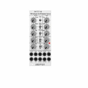
Otros clientes también compraron...
Doepfer A-111-6 Miniature Synthesiser Voice Slim Line Series Module (silver) (synth voice synth module)
Cat: 731937 Rel: 15 Nov 19
Complete miniature monophonic synthesiser module - 10HP
Notes: VCO:
- Tune: manual tune control (with an internal jumper the range can be set to ~ +/-1 half an octave or ~ +/-2.5 octaves)
- Oct: range switch -1 / 0 / +1 octave
- Mod: modulation depth (attenuator wired to the Mod. socket)
- Dest: switch that is used to address the modulation to frequency modulation (position FM) or pulsewidth modulation (positon PM), in centre positon no modulation
- PW: manual pulsewidth control for rectangle waveform, PW can be also modulated by the Mod. input as mentioned above
- Wave: waveform switch (sawtooth / off / triangle), the sum of the waveform chosen by this switch and the rectangle is fed into the VCF (to turn the rectangle off the PW control has to be set fully CCW or fully CW)
- 1V/Oct. (socket): external CV input for VCO frequency (1V/octave)
- Access to internal bus CV (via jumper, optional, please remove the bus jumper if this feature is not used to avoid unwanted frequency modulation as then the unused CV line of the bus works as a kind of antenna)
- Triangle core VCO, frequency range about 32Hz ... 8kHz
Balance unit:
- The balance unit is made of two VCAs which are controlled by the sum of manual Balance control and the balance CV input in the opposite direction.
- The audio input of VCA1 is hard-wired to the VCO output, audio input 2 is connected to the socket Ext.In.
- The output of the balance unit is used as audio input for the VCF
- Bal.: manual balance control, fully CCW the internal VCO is used, fully CW the external signal (Ext.In) is used, at centre position both signals have about the same level
- CV Bal.: CV input for balance (range about 0...+5V)
- Ext. In: external audio input for VCA2, about 5 Vpp level required for similar loudness as the internal VCO
- This socket is normalled to the internal VCO suboctave f/2 signal (rectangle with half the frequency), if no external signal is applied the suboctave signal is used as the second signal for the balance unit
VCF:
- 24 dB low pass
- Frq: manual frequency control
- FM1: frequency modulation depth (attenuator wired to the VCF FM1 socket, the socket is normalled to the internal Envelope signal and then FM1 controls the modulation depth of the internal envelope applied to the filter)
- FM2 (socket) : second CV input for VCF without attenuator (about 1V/octave), can be used e.g. for VCF tracking by connecting the same CV which is used also for the VCO frequency
- Res: manual resonance control (up to self oscillation)
- If the VCO is turned off (waveform switch = centre position, pulsewidth control = fully CCW or CW) and the VCF resonance is set to maximum the module can be used as a sine oscillator, the tracking at socket VCF FM2 is about 1V/octave (not as precise as the VCO but much better than most other filters)
- ~ 11 octaves frequency range (~ 10 Hz ... 20kHz)
VCA:
- Gain: manual amplitude control (initial gain), can be used to open the VCA without envelope signal
- VCA (switch): used to switch between gate and envelope as control signal for the VCA, in centre position the VCA is not controlled by envelope or gate
- Note: when gate is used the VCA is controlled directly by the gate signal (i.e. hard on/off), this may lead to clicking noise under certain conditions (especially with low VCO/VCF frequencies)
- Special control scale: exponential scale in the range from about -20dB to -80/90dB, linear scale from about -20dB to 0dB
- Remark: this special control scale results in a loudness behaviour that is a bit different from pure linear or exponential VCAs
- Out: audio output of the module (= VCA output)
Envelope:
- Gate (socket): Gate input (min. +5V), can be normalled to the bus gate signal by means of a jumper
- Att: manual control for Attack
- D/R: manual control for Decay/Release
- Env. (switch): used to switch between A/D, ADSR and A/R mode of the envelope generator, in centre position (ADSR) the sustain level is fixed to about 50%
- Envelope (socket): envelope output (about +10V)
- CVT (socket): CV input for time control, by means of two internal jumpers one can select which time parameters are controlled by the CVT input (e.g. A only or D/R only or A/D/R) and in which direction (i.e. if an increasing CVT shortens or stretches the time parameter in question)
- Envelope LED display
- Attack time range: ~ 1ms ... 5 sec (can be extended by using the CVT input)
- Decay/Release time range: ~ 1ms ... 15 sec (can be extended by using the CVT input)
… Read more- Tune: manual tune control (with an internal jumper the range can be set to ~ +/-1 half an octave or ~ +/-2.5 octaves)
- Oct: range switch -1 / 0 / +1 octave
- Mod: modulation depth (attenuator wired to the Mod. socket)
- Dest: switch that is used to address the modulation to frequency modulation (position FM) or pulsewidth modulation (positon PM), in centre positon no modulation
- PW: manual pulsewidth control for rectangle waveform, PW can be also modulated by the Mod. input as mentioned above
- Wave: waveform switch (sawtooth / off / triangle), the sum of the waveform chosen by this switch and the rectangle is fed into the VCF (to turn the rectangle off the PW control has to be set fully CCW or fully CW)
- 1V/Oct. (socket): external CV input for VCO frequency (1V/octave)
- Access to internal bus CV (via jumper, optional, please remove the bus jumper if this feature is not used to avoid unwanted frequency modulation as then the unused CV line of the bus works as a kind of antenna)
- Triangle core VCO, frequency range about 32Hz ... 8kHz
Balance unit:
- The balance unit is made of two VCAs which are controlled by the sum of manual Balance control and the balance CV input in the opposite direction.
- The audio input of VCA1 is hard-wired to the VCO output, audio input 2 is connected to the socket Ext.In.
- The output of the balance unit is used as audio input for the VCF
- Bal.: manual balance control, fully CCW the internal VCO is used, fully CW the external signal (Ext.In) is used, at centre position both signals have about the same level
- CV Bal.: CV input for balance (range about 0...+5V)
- Ext. In: external audio input for VCA2, about 5 Vpp level required for similar loudness as the internal VCO
- This socket is normalled to the internal VCO suboctave f/2 signal (rectangle with half the frequency), if no external signal is applied the suboctave signal is used as the second signal for the balance unit
VCF:
- 24 dB low pass
- Frq: manual frequency control
- FM1: frequency modulation depth (attenuator wired to the VCF FM1 socket, the socket is normalled to the internal Envelope signal and then FM1 controls the modulation depth of the internal envelope applied to the filter)
- FM2 (socket) : second CV input for VCF without attenuator (about 1V/octave), can be used e.g. for VCF tracking by connecting the same CV which is used also for the VCO frequency
- Res: manual resonance control (up to self oscillation)
- If the VCO is turned off (waveform switch = centre position, pulsewidth control = fully CCW or CW) and the VCF resonance is set to maximum the module can be used as a sine oscillator, the tracking at socket VCF FM2 is about 1V/octave (not as precise as the VCO but much better than most other filters)
- ~ 11 octaves frequency range (~ 10 Hz ... 20kHz)
VCA:
- Gain: manual amplitude control (initial gain), can be used to open the VCA without envelope signal
- VCA (switch): used to switch between gate and envelope as control signal for the VCA, in centre position the VCA is not controlled by envelope or gate
- Note: when gate is used the VCA is controlled directly by the gate signal (i.e. hard on/off), this may lead to clicking noise under certain conditions (especially with low VCO/VCF frequencies)
- Special control scale: exponential scale in the range from about -20dB to -80/90dB, linear scale from about -20dB to 0dB
- Remark: this special control scale results in a loudness behaviour that is a bit different from pure linear or exponential VCAs
- Out: audio output of the module (= VCA output)
Envelope:
- Gate (socket): Gate input (min. +5V), can be normalled to the bus gate signal by means of a jumper
- Att: manual control for Attack
- D/R: manual control for Decay/Release
- Env. (switch): used to switch between A/D, ADSR and A/R mode of the envelope generator, in centre position (ADSR) the sustain level is fixed to about 50%
- Envelope (socket): envelope output (about +10V)
- CVT (socket): CV input for time control, by means of two internal jumpers one can select which time parameters are controlled by the CVT input (e.g. A only or D/R only or A/D/R) and in which direction (i.e. if an increasing CVT shortens or stretches the time parameter in question)
- Envelope LED display
- Attack time range: ~ 1ms ... 5 sec (can be extended by using the CVT input)
- Decay/Release time range: ~ 1ms ... 15 sec (can be extended by using the CVT input)
1 in stock $192.83
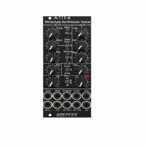
Otros clientes también compraron...
Doepfer A-111-6v Miniature Synthesiser Voice Vintage Edition Module (black) (synth voice synth module)
Cat: 749811 Rel: 15 Nov 19
Complete miniature monophonic synthesiser module - 10HP
Notes: VCO:
- Tune: manual tune control (with an internal jumper the range can be set to ~ +/-1 half an octave or ~ +/-2.5 octaves)
- Oct: range switch -1 / 0 / +1 octave
- Mod: modulation depth (attenuator wired to the Mod. socket)
- Dest: switch that is used to address the modulation to frequency modulation (position FM) or pulsewidth modulation (positon PM), in centre positon no modulation
- PW: manual pulsewidth control for rectangle waveform, PW can be also modulated by the Mod. input as mentioned above
- Wave: waveform switch (sawtooth / off / triangle), the sum of the waveform chosen by this switch and the rectangle is fed into the VCF (to turn the rectangle off the PW control has to be set fully CCW or fully CW)
- 1V/Oct. (socket): external CV input for VCO frequency (1V/octave)
- Access to internal bus CV (via jumper, optional, please remove the bus jumper if this feature is not used to avoid unwanted frequency modulation as then the unused CV line of the bus works as a kind of antenna)
- Triangle core VCO, frequency range about 32Hz ... 8kHz
Balance unit:
- The balance unit is made of two VCAs which are controlled by the sum of manual Balance control and the balance CV input in the opposite direction.
- The audio input of VCA1 is hard-wired to the VCO output, audio input 2 is connected to the socket Ext.In.
- The output of the balance unit is used as audio input for the VCF
- Bal.: manual balance control, fully CCW the internal VCO is used, fully CW the external signal (Ext.In) is used, at centre position both signals have about the same level
- CV Bal.: CV input for balance (range about 0...+5V)
- Ext. In: external audio input for VCA2, about 5 Vpp level required for similar loudness as the internal VCO
- This socket is normalled to the internal VCO suboctave f/2 signal (rectangle with half the frequency), if no external signal is applied the suboctave signal is used as the second signal for the balance unit
VCF:
- 24 dB low pass
- Frq: manual frequency control
- FM1: frequency modulation depth (attenuator wired to the VCF FM1 socket, the socket is normalled to the internal Envelope signal and then FM1 controls the modulation depth of the internal envelope applied to the filter)
- FM2 (socket) : second CV input for VCF without attenuator (about 1V/octave), can be used e.g. for VCF tracking by connecting the same CV which is used also for the VCO frequency
- Res: manual resonance control (up to self oscillation)
- If the VCO is turned off (waveform switch = centre position, pulsewidth control = fully CCW or CW) and the VCF resonance is set to maximum the module can be used as a sine oscillator, the tracking at socket VCF FM2 is about 1V/octave (not as precise as the VCO but much better than most other filters)
- ~ 11 octaves frequency range (~ 10 Hz ... 20kHz)
VCA:
- Gain: manual amplitude control (initial gain), can be used to open the VCA without envelope signal
- VCA (switch): used to switch between gate and envelope as control signal for the VCA, in centre position the VCA is not controlled by envelope or gate
- Note: when gate is used the VCA is controlled directly by the gate signal (i.e. hard on/off), this may lead to clicking noise under certain conditions (especially with low VCO/VCF frequencies)
- Special control scale: exponential scale in the range from about -20dB to -80/90dB, linear scale from about -20dB to 0dB
- Remark: this special control scale results in a loudness behaviour that is a bit different from pure linear or exponential VCAs
- Out: audio output of the module (= VCA output)
Envelope:
- Gate (socket): Gate input (min. +5V), can be normalled to the bus gate signal by means of a jumper
- Att: manual control for Attack
- D/R: manual control for Decay/Release
- Env. (switch): used to switch between A/D, ADSR and A/R mode of the envelope generator, in centre position (ADSR) the sustain level is fixed to about 50%
- Envelope (socket): envelope output (about +10V)
- CVT (socket): CV input for time control, by means of two internal jumpers one can select which time parameters are controlled by the CVT input (e.g. A only or D/R only or A/D/R) and in which direction (i.e. if an increasing CVT shortens or stretches the time parameter in question)
- Envelope LED display
- Attack time range: ~ 1ms ... 5 sec (can be extended by using the CVT input)
- Decay/Release time range: ~ 1ms ... 15 sec (can be extended by using the CVT input)
… Read more- Tune: manual tune control (with an internal jumper the range can be set to ~ +/-1 half an octave or ~ +/-2.5 octaves)
- Oct: range switch -1 / 0 / +1 octave
- Mod: modulation depth (attenuator wired to the Mod. socket)
- Dest: switch that is used to address the modulation to frequency modulation (position FM) or pulsewidth modulation (positon PM), in centre positon no modulation
- PW: manual pulsewidth control for rectangle waveform, PW can be also modulated by the Mod. input as mentioned above
- Wave: waveform switch (sawtooth / off / triangle), the sum of the waveform chosen by this switch and the rectangle is fed into the VCF (to turn the rectangle off the PW control has to be set fully CCW or fully CW)
- 1V/Oct. (socket): external CV input for VCO frequency (1V/octave)
- Access to internal bus CV (via jumper, optional, please remove the bus jumper if this feature is not used to avoid unwanted frequency modulation as then the unused CV line of the bus works as a kind of antenna)
- Triangle core VCO, frequency range about 32Hz ... 8kHz
Balance unit:
- The balance unit is made of two VCAs which are controlled by the sum of manual Balance control and the balance CV input in the opposite direction.
- The audio input of VCA1 is hard-wired to the VCO output, audio input 2 is connected to the socket Ext.In.
- The output of the balance unit is used as audio input for the VCF
- Bal.: manual balance control, fully CCW the internal VCO is used, fully CW the external signal (Ext.In) is used, at centre position both signals have about the same level
- CV Bal.: CV input for balance (range about 0...+5V)
- Ext. In: external audio input for VCA2, about 5 Vpp level required for similar loudness as the internal VCO
- This socket is normalled to the internal VCO suboctave f/2 signal (rectangle with half the frequency), if no external signal is applied the suboctave signal is used as the second signal for the balance unit
VCF:
- 24 dB low pass
- Frq: manual frequency control
- FM1: frequency modulation depth (attenuator wired to the VCF FM1 socket, the socket is normalled to the internal Envelope signal and then FM1 controls the modulation depth of the internal envelope applied to the filter)
- FM2 (socket) : second CV input for VCF without attenuator (about 1V/octave), can be used e.g. for VCF tracking by connecting the same CV which is used also for the VCO frequency
- Res: manual resonance control (up to self oscillation)
- If the VCO is turned off (waveform switch = centre position, pulsewidth control = fully CCW or CW) and the VCF resonance is set to maximum the module can be used as a sine oscillator, the tracking at socket VCF FM2 is about 1V/octave (not as precise as the VCO but much better than most other filters)
- ~ 11 octaves frequency range (~ 10 Hz ... 20kHz)
VCA:
- Gain: manual amplitude control (initial gain), can be used to open the VCA without envelope signal
- VCA (switch): used to switch between gate and envelope as control signal for the VCA, in centre position the VCA is not controlled by envelope or gate
- Note: when gate is used the VCA is controlled directly by the gate signal (i.e. hard on/off), this may lead to clicking noise under certain conditions (especially with low VCO/VCF frequencies)
- Special control scale: exponential scale in the range from about -20dB to -80/90dB, linear scale from about -20dB to 0dB
- Remark: this special control scale results in a loudness behaviour that is a bit different from pure linear or exponential VCAs
- Out: audio output of the module (= VCA output)
Envelope:
- Gate (socket): Gate input (min. +5V), can be normalled to the bus gate signal by means of a jumper
- Att: manual control for Attack
- D/R: manual control for Decay/Release
- Env. (switch): used to switch between A/D, ADSR and A/R mode of the envelope generator, in centre position (ADSR) the sustain level is fixed to about 50%
- Envelope (socket): envelope output (about +10V)
- CVT (socket): CV input for time control, by means of two internal jumpers one can select which time parameters are controlled by the CVT input (e.g. A only or D/R only or A/D/R) and in which direction (i.e. if an increasing CVT shortens or stretches the time parameter in question)
- Envelope LED display
- Attack time range: ~ 1ms ... 5 sec (can be extended by using the CVT input)
- Decay/Release time range: ~ 1ms ... 15 sec (can be extended by using the CVT input)
1 in stock $206.40
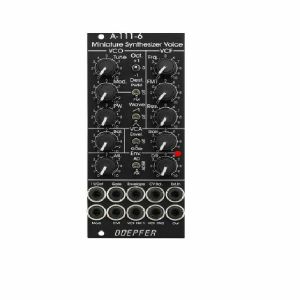
Otros clientes también compraron...
Doepfer A-111-6v Miniature Synthesiser Voice Vintage Edition Module (black) (B-STOCK) (synth voice synth module)
Cat: 904371 Rel: 15 Nov 19
B-STOCK: Slight surface marks
Notes: ***B-STOCK: Slight surface marks ***
VCO:
- Tune: manual tune control (with an internal jumper the range can be set to ~ +/-1 half an octave or ~ +/-2.5 octaves)
- Oct: range switch -1 / 0 / +1 octave
- Mod: modulation depth (attenuator wired to the Mod. socket)
- Dest: switch that is used to address the modulation to frequency modulation (position FM) or pulsewidth modulation (positon PM), in centre positon no modulation
- PW: manual pulsewidth control for rectangle waveform, PW can be also modulated by the Mod. input as mentioned above
- Wave: waveform switch (sawtooth / off / triangle), the sum of the waveform chosen by this switch and the rectangle is fed into the VCF (to turn the rectangle off the PW control has to be set fully CCW or fully CW)
- 1V/Oct. (socket): external CV input for VCO frequency (1V/octave)
- Access to internal bus CV (via jumper, optional, please remove the bus jumper if this feature is not used to avoid unwanted frequency modulation as then the unused CV line of the bus works as a kind of antenna)
- Triangle core VCO, frequency range about 32Hz ... 8kHz
Balance unit:
- The balance unit is made of two VCAs which are controlled by the sum of manual Balance control and the balance CV input in the opposite direction.
- The audio input of VCA1 is hard-wired to the VCO output, audio input 2 is connected to the socket Ext.In.
- The output of the balance unit is used as audio input for the VCF
- Bal.: manual balance control, fully CCW the internal VCO is used, fully CW the external signal (Ext.In) is used, at centre position both signals have about the same level
- CV Bal.: CV input for balance (range about 0...+5V)
- Ext. In: external audio input for VCA2, about 5 Vpp level required for similar loudness as the internal VCO
- This socket is normalled to the internal VCO suboctave f/2 signal (rectangle with half the frequency), if no external signal is applied the suboctave signal is used as the second signal for the balance unit
VCF:
- 24 dB low pass
- Frq: manual frequency control
- FM1: frequency modulation depth (attenuator wired to the VCF FM1 socket, the socket is normalled to the internal Envelope signal and then FM1 controls the modulation depth of the internal envelope applied to the filter)
- FM2 (socket) : second CV input for VCF without attenuator (about 1V/octave), can be used e.g. for VCF tracking by connecting the same CV which is used also for the VCO frequency
- Res: manual resonance control (up to self oscillation)
- If the VCO is turned off (waveform switch = centre position, pulsewidth control = fully CCW or CW) and the VCF resonance is set to maximum the module can be used as a sine oscillator, the tracking at socket VCF FM2 is about 1V/octave (not as precise as the VCO but much better than most other filters)
- ~ 11 octaves frequency range (~ 10 Hz ... 20kHz)
VCA:
- Gain: manual amplitude control (initial gain), can be used to open the VCA without envelope signal
- VCA (switch): used to switch between gate and envelope as control signal for the VCA, in centre position the VCA is not controlled by envelope or gate
- Note: when gate is used the VCA is controlled directly by the gate signal (i.e. hard on/off), this may lead to clicking noise under certain conditions (especially with low VCO/VCF frequencies)
- Special control scale: exponential scale in the range from about -20dB to -80/90dB, linear scale from about -20dB to 0dB
- Remark: this special control scale results in a loudness behaviour that is a bit different from pure linear or exponential VCAs
- Out: audio output of the module (= VCA output)
Envelope:
- Gate (socket): Gate input (min. +5V), can be normalled to the bus gate signal by means of a jumper
- Att: manual control for Attack
- D/R: manual control for Decay/Release
- Env. (switch): used to switch between A/D, ADSR and A/R mode of the envelope generator, in centre position (ADSR) the sustain level is fixed to about 50%
- Envelope (socket): envelope output (about +10V)
- CVT (socket): CV input for time control, by means of two internal jumpers one can select which time parameters are controlled by the CVT input (e.g. A only or D/R only or A/D/R) and in which direction (i.e. if an increasing CVT shortens or stretches the time parameter in question)
- Envelope LED display
- Attack time range: ~ 1ms ... 5 sec (can be extended by using the CVT input)
- Decay/Release time range: ~ 1ms ... 15 sec (can be extended by using the CVT input)
… Read moreVCO:
- Tune: manual tune control (with an internal jumper the range can be set to ~ +/-1 half an octave or ~ +/-2.5 octaves)
- Oct: range switch -1 / 0 / +1 octave
- Mod: modulation depth (attenuator wired to the Mod. socket)
- Dest: switch that is used to address the modulation to frequency modulation (position FM) or pulsewidth modulation (positon PM), in centre positon no modulation
- PW: manual pulsewidth control for rectangle waveform, PW can be also modulated by the Mod. input as mentioned above
- Wave: waveform switch (sawtooth / off / triangle), the sum of the waveform chosen by this switch and the rectangle is fed into the VCF (to turn the rectangle off the PW control has to be set fully CCW or fully CW)
- 1V/Oct. (socket): external CV input for VCO frequency (1V/octave)
- Access to internal bus CV (via jumper, optional, please remove the bus jumper if this feature is not used to avoid unwanted frequency modulation as then the unused CV line of the bus works as a kind of antenna)
- Triangle core VCO, frequency range about 32Hz ... 8kHz
Balance unit:
- The balance unit is made of two VCAs which are controlled by the sum of manual Balance control and the balance CV input in the opposite direction.
- The audio input of VCA1 is hard-wired to the VCO output, audio input 2 is connected to the socket Ext.In.
- The output of the balance unit is used as audio input for the VCF
- Bal.: manual balance control, fully CCW the internal VCO is used, fully CW the external signal (Ext.In) is used, at centre position both signals have about the same level
- CV Bal.: CV input for balance (range about 0...+5V)
- Ext. In: external audio input for VCA2, about 5 Vpp level required for similar loudness as the internal VCO
- This socket is normalled to the internal VCO suboctave f/2 signal (rectangle with half the frequency), if no external signal is applied the suboctave signal is used as the second signal for the balance unit
VCF:
- 24 dB low pass
- Frq: manual frequency control
- FM1: frequency modulation depth (attenuator wired to the VCF FM1 socket, the socket is normalled to the internal Envelope signal and then FM1 controls the modulation depth of the internal envelope applied to the filter)
- FM2 (socket) : second CV input for VCF without attenuator (about 1V/octave), can be used e.g. for VCF tracking by connecting the same CV which is used also for the VCO frequency
- Res: manual resonance control (up to self oscillation)
- If the VCO is turned off (waveform switch = centre position, pulsewidth control = fully CCW or CW) and the VCF resonance is set to maximum the module can be used as a sine oscillator, the tracking at socket VCF FM2 is about 1V/octave (not as precise as the VCO but much better than most other filters)
- ~ 11 octaves frequency range (~ 10 Hz ... 20kHz)
VCA:
- Gain: manual amplitude control (initial gain), can be used to open the VCA without envelope signal
- VCA (switch): used to switch between gate and envelope as control signal for the VCA, in centre position the VCA is not controlled by envelope or gate
- Note: when gate is used the VCA is controlled directly by the gate signal (i.e. hard on/off), this may lead to clicking noise under certain conditions (especially with low VCO/VCF frequencies)
- Special control scale: exponential scale in the range from about -20dB to -80/90dB, linear scale from about -20dB to 0dB
- Remark: this special control scale results in a loudness behaviour that is a bit different from pure linear or exponential VCAs
- Out: audio output of the module (= VCA output)
Envelope:
- Gate (socket): Gate input (min. +5V), can be normalled to the bus gate signal by means of a jumper
- Att: manual control for Attack
- D/R: manual control for Decay/Release
- Env. (switch): used to switch between A/D, ADSR and A/R mode of the envelope generator, in centre position (ADSR) the sustain level is fixed to about 50%
- Envelope (socket): envelope output (about +10V)
- CVT (socket): CV input for time control, by means of two internal jumpers one can select which time parameters are controlled by the CVT input (e.g. A only or D/R only or A/D/R) and in which direction (i.e. if an increasing CVT shortens or stretches the time parameter in question)
- Envelope LED display
- Attack time range: ~ 1ms ... 5 sec (can be extended by using the CVT input)
- Decay/Release time range: ~ 1ms ... 15 sec (can be extended by using the CVT input)
out of stock $180.63

Otros clientes también compraron...
Doepfer A-111-6v Miniature Synthesiser Voice Vintage Edition Module (black) (B-STOCK) (synth voice synth module)
Cat: 970408 Rel: 01 Jan 90
B-STOCK: Slight dent om the edge, otherwise in perfect condition
Notes: ***B-STOCK: Slight dent om the edge, otherwise in perfect condition***
VCO:
- Tune: manual tune control (with an internal jumper the range can be set to ~ +/-1 half an octave or ~ +/-2.5 octaves)
- Oct: range switch -1 / 0 / +1 octave
- Mod: modulation depth (attenuator wired to the Mod. socket)
- Dest: switch that is used to address the modulation to frequency modulation (position FM) or pulsewidth modulation (positon PM), in centre positon no modulation
- PW: manual pulsewidth control for rectangle waveform, PW can be also modulated by the Mod. input as mentioned above
- Wave: waveform switch (sawtooth / off / triangle), the sum of the waveform chosen by this switch and the rectangle is fed into the VCF (to turn the rectangle off the PW control has to be set fully CCW or fully CW)
- 1V/Oct. (socket): external CV input for VCO frequency (1V/octave)
- Access to internal bus CV (via jumper, optional, please remove the bus jumper if this feature is not used to avoid unwanted frequency modulation as then the unused CV line of the bus works as a kind of antenna)
- Triangle core VCO, frequency range about 32Hz ... 8kHz
Balance unit:
- The balance unit is made of two VCAs which are controlled by the sum of manual Balance control and the balance CV input in the opposite direction.
- The audio input of VCA1 is hard-wired to the VCO output, audio input 2 is connected to the socket Ext.In.
- The output of the balance unit is used as audio input for the VCF
- Bal.: manual balance control, fully CCW the internal VCO is used, fully CW the external signal (Ext.In) is used, at centre position both signals have about the same level
- CV Bal.: CV input for balance (range about 0...+5V)
- Ext. In: external audio input for VCA2, about 5 Vpp level required for similar loudness as the internal VCO
- This socket is normalled to the internal VCO suboctave f/2 signal (rectangle with half the frequency), if no external signal is applied the suboctave signal is used as the second signal for the balance unit
VCF:
- 24 dB low pass
- Frq: manual frequency control
- FM1: frequency modulation depth (attenuator wired to the VCF FM1 socket, the socket is normalled to the internal Envelope signal and then FM1 controls the modulation depth of the internal envelope applied to the filter)
- FM2 (socket) : second CV input for VCF without attenuator (about 1V/octave), can be used e.g. for VCF tracking by connecting the same CV which is used also for the VCO frequency
- Res: manual resonance control (up to self oscillation)
- If the VCO is turned off (waveform switch = centre position, pulsewidth control = fully CCW or CW) and the VCF resonance is set to maximum the module can be used as a sine oscillator, the tracking at socket VCF FM2 is about 1V/octave (not as precise as the VCO but much better than most other filters)
- ~ 11 octaves frequency range (~ 10 Hz ... 20kHz)
VCA:
- Gain: manual amplitude control (initial gain), can be used to open the VCA without envelope signal
- VCA (switch): used to switch between gate and envelope as control signal for the VCA, in centre position the VCA is not controlled by envelope or gate
- Note: when gate is used the VCA is controlled directly by the gate signal (i.e. hard on/off), this may lead to clicking noise under certain conditions (especially with low VCO/VCF frequencies)
- Special control scale: exponential scale in the range from about -20dB to -80/90dB, linear scale from about -20dB to 0dB
- Remark: this special control scale results in a loudness behaviour that is a bit different from pure linear or exponential VCAs
- Out: audio output of the module (= VCA output)
Envelope:
- Gate (socket): Gate input (min. +5V), can be normalled to the bus gate signal by means of a jumper
- Att: manual control for Attack
- D/R: manual control for Decay/Release
- Env. (switch): used to switch between A/D, ADSR and A/R mode of the envelope generator, in centre position (ADSR) the sustain level is fixed to about 50%
- Envelope (socket): envelope output (about +10V)
- CVT (socket): CV input for time control, by means of two internal jumpers one can select which time parameters are controlled by the CVT input (e.g. A only or D/R only or A/D/R) and in which direction (i.e. if an increasing CVT shortens or stretches the time parameter in question)
- Envelope LED display
- Attack time range: ~ 1ms ... 5 sec (can be extended by using the CVT input)
- Decay/Release time range: ~ 1ms ... 15 sec (can be extended by using the CVT input)
… Read moreVCO:
- Tune: manual tune control (with an internal jumper the range can be set to ~ +/-1 half an octave or ~ +/-2.5 octaves)
- Oct: range switch -1 / 0 / +1 octave
- Mod: modulation depth (attenuator wired to the Mod. socket)
- Dest: switch that is used to address the modulation to frequency modulation (position FM) or pulsewidth modulation (positon PM), in centre positon no modulation
- PW: manual pulsewidth control for rectangle waveform, PW can be also modulated by the Mod. input as mentioned above
- Wave: waveform switch (sawtooth / off / triangle), the sum of the waveform chosen by this switch and the rectangle is fed into the VCF (to turn the rectangle off the PW control has to be set fully CCW or fully CW)
- 1V/Oct. (socket): external CV input for VCO frequency (1V/octave)
- Access to internal bus CV (via jumper, optional, please remove the bus jumper if this feature is not used to avoid unwanted frequency modulation as then the unused CV line of the bus works as a kind of antenna)
- Triangle core VCO, frequency range about 32Hz ... 8kHz
Balance unit:
- The balance unit is made of two VCAs which are controlled by the sum of manual Balance control and the balance CV input in the opposite direction.
- The audio input of VCA1 is hard-wired to the VCO output, audio input 2 is connected to the socket Ext.In.
- The output of the balance unit is used as audio input for the VCF
- Bal.: manual balance control, fully CCW the internal VCO is used, fully CW the external signal (Ext.In) is used, at centre position both signals have about the same level
- CV Bal.: CV input for balance (range about 0...+5V)
- Ext. In: external audio input for VCA2, about 5 Vpp level required for similar loudness as the internal VCO
- This socket is normalled to the internal VCO suboctave f/2 signal (rectangle with half the frequency), if no external signal is applied the suboctave signal is used as the second signal for the balance unit
VCF:
- 24 dB low pass
- Frq: manual frequency control
- FM1: frequency modulation depth (attenuator wired to the VCF FM1 socket, the socket is normalled to the internal Envelope signal and then FM1 controls the modulation depth of the internal envelope applied to the filter)
- FM2 (socket) : second CV input for VCF without attenuator (about 1V/octave), can be used e.g. for VCF tracking by connecting the same CV which is used also for the VCO frequency
- Res: manual resonance control (up to self oscillation)
- If the VCO is turned off (waveform switch = centre position, pulsewidth control = fully CCW or CW) and the VCF resonance is set to maximum the module can be used as a sine oscillator, the tracking at socket VCF FM2 is about 1V/octave (not as precise as the VCO but much better than most other filters)
- ~ 11 octaves frequency range (~ 10 Hz ... 20kHz)
VCA:
- Gain: manual amplitude control (initial gain), can be used to open the VCA without envelope signal
- VCA (switch): used to switch between gate and envelope as control signal for the VCA, in centre position the VCA is not controlled by envelope or gate
- Note: when gate is used the VCA is controlled directly by the gate signal (i.e. hard on/off), this may lead to clicking noise under certain conditions (especially with low VCO/VCF frequencies)
- Special control scale: exponential scale in the range from about -20dB to -80/90dB, linear scale from about -20dB to 0dB
- Remark: this special control scale results in a loudness behaviour that is a bit different from pure linear or exponential VCAs
- Out: audio output of the module (= VCA output)
Envelope:
- Gate (socket): Gate input (min. +5V), can be normalled to the bus gate signal by means of a jumper
- Att: manual control for Attack
- D/R: manual control for Decay/Release
- Env. (switch): used to switch between A/D, ADSR and A/R mode of the envelope generator, in centre position (ADSR) the sustain level is fixed to about 50%
- Envelope (socket): envelope output (about +10V)
- CVT (socket): CV input for time control, by means of two internal jumpers one can select which time parameters are controlled by the CVT input (e.g. A only or D/R only or A/D/R) and in which direction (i.e. if an increasing CVT shortens or stretches the time parameter in question)
- Envelope LED display
- Attack time range: ~ 1ms ... 5 sec (can be extended by using the CVT input)
- Decay/Release time range: ~ 1ms ... 15 sec (can be extended by using the CVT input)
out of stock $159.19

Otros clientes también compraron...
Doepfer A-112 Sampler VC Sampler & Wavetable Oscillator Module (silver) (sampler synth module)
Cat: 671607 Rel: 29 Nov 17
Voltage-controlled sampler & wavetable oscillator module - 10HP
Notes: Module A-112 is the combination of a voltage controlled 8 Bit Sampler and a wavetable oscillator. On top of it the module is able to generate some special effects. A-112 was designed as an additional sound source with the typical sounds of the early 8 bit samplers and is not comparable with the modern polyphonic MIDI samplers available on the market.
Sampling mode: 8 bit audio resolution, 128kB memory in 2 banks 64kB each (equivalent to 2 seconds of sampling time for each bank with 32 kHz sampling rate), audio input with attenuator, overload display in record mode (gate LED), possibility of MIDI Dump to store sounds in a computer via MIDI, non-volatile memory for the 2 samples in the module, manual tune control for adjustment of sampling rate for record and play, CV input (~ 1V/Oct), both manual tune and CV determine the sampling rate respectively the pitch (pitch range is 5 octaves), gate input (not a trigger: the sample starts at the positive edge of the gate signal and is played as long as gate is high or until the end of the sample is reached), manual Gate button, non-filtered audio output (thus quantizing noise can be used as an element of the sound intentionally).
Wavetable mode: special appearance of the sampling mode when playing a sample, the audio input is now used as a second control voltage input for moving through the sample in 256 byte wide loops (wavetables). The control voltage required to move through all wavetables applied to the input "Wave CV In" is in the range -2.5V (wavetable 1) ... 0V (wavetable 127) ... +2.5V (wavetable 256) when control "Atten." is set fully clockwise. To achieve the typical wavetable oscillator sounds the sampling memory must contain corresponding wavetable data (e.g. loaded via MIDI dump). These data contain a set of wavetables with different harmonic content (e.g. a filter sweep) to get the typical wavetable sound while moving through the tables via CV. But you may also use a "normal" sample and go through the sample with CV to obtain partially amazing sounds never heard before. You may use for example sampled speech and go with CV through the syllables or speech shreds to get really very extreme sounds. An ideal addition for this feature is the Offset/Attenuator module A-183-2 which can be used to adjust the position of the wavetable (Offset) and the modulation depth (Att.). The corresponding jumper of the A-183-2 has to be set to bipolar offset (as the A-112 requires -2.5V...+2.5V to pass through all 256 wavetables). As modulation source an LFO (A-145, A-146, A-147, A-143-3), ADSR (A-140, A-141, A-142, A-143-1/2) or a random voltage (A-118, A-149-1) may be used. Even a ribbon controller (A-198 or R2M), the Theremin module A-178, the Joystick A-174 or the Wheels module A-174-2 are useful to drive through the wavetables.
Effects: Additionally, the module offers - in a way free of charge - some effects like delay, reverse delay, pitch shifting or freeze. But it has to be pointed out that due to the 8 bit audio resolution these effects are not comparable to high quality effect units and should be understand as an extra for nothing. The A-112 is not an effects unit!
The sampling time of the A-112 is about 1...30 seconds corresponding to a sampling frequency range of about 60kHz...2kHz (64kB@60kHz ~ 1 s, 64kB@2kHz ~ 30 s).
Technical note: the module uses a battery for the non-volatile storage of the sampling data. Batteries have a limited lifespan and have to be inspected at least every two years. For details please refer to the FAQ page of our website: Lifespan of rechargeable batteries (used for memory backup).
Width: 10HP / 50.5 mm
Depth: 100 mm (measured from the rear side of the front panel)
Current: +50mA (+12V) / -20mA (-12V)
… Read moreSampling mode: 8 bit audio resolution, 128kB memory in 2 banks 64kB each (equivalent to 2 seconds of sampling time for each bank with 32 kHz sampling rate), audio input with attenuator, overload display in record mode (gate LED), possibility of MIDI Dump to store sounds in a computer via MIDI, non-volatile memory for the 2 samples in the module, manual tune control for adjustment of sampling rate for record and play, CV input (~ 1V/Oct), both manual tune and CV determine the sampling rate respectively the pitch (pitch range is 5 octaves), gate input (not a trigger: the sample starts at the positive edge of the gate signal and is played as long as gate is high or until the end of the sample is reached), manual Gate button, non-filtered audio output (thus quantizing noise can be used as an element of the sound intentionally).
Wavetable mode: special appearance of the sampling mode when playing a sample, the audio input is now used as a second control voltage input for moving through the sample in 256 byte wide loops (wavetables). The control voltage required to move through all wavetables applied to the input "Wave CV In" is in the range -2.5V (wavetable 1) ... 0V (wavetable 127) ... +2.5V (wavetable 256) when control "Atten." is set fully clockwise. To achieve the typical wavetable oscillator sounds the sampling memory must contain corresponding wavetable data (e.g. loaded via MIDI dump). These data contain a set of wavetables with different harmonic content (e.g. a filter sweep) to get the typical wavetable sound while moving through the tables via CV. But you may also use a "normal" sample and go through the sample with CV to obtain partially amazing sounds never heard before. You may use for example sampled speech and go with CV through the syllables or speech shreds to get really very extreme sounds. An ideal addition for this feature is the Offset/Attenuator module A-183-2 which can be used to adjust the position of the wavetable (Offset) and the modulation depth (Att.). The corresponding jumper of the A-183-2 has to be set to bipolar offset (as the A-112 requires -2.5V...+2.5V to pass through all 256 wavetables). As modulation source an LFO (A-145, A-146, A-147, A-143-3), ADSR (A-140, A-141, A-142, A-143-1/2) or a random voltage (A-118, A-149-1) may be used. Even a ribbon controller (A-198 or R2M), the Theremin module A-178, the Joystick A-174 or the Wheels module A-174-2 are useful to drive through the wavetables.
Effects: Additionally, the module offers - in a way free of charge - some effects like delay, reverse delay, pitch shifting or freeze. But it has to be pointed out that due to the 8 bit audio resolution these effects are not comparable to high quality effect units and should be understand as an extra for nothing. The A-112 is not an effects unit!
The sampling time of the A-112 is about 1...30 seconds corresponding to a sampling frequency range of about 60kHz...2kHz (64kB@60kHz ~ 1 s, 64kB@2kHz ~ 30 s).
Technical note: the module uses a battery for the non-volatile storage of the sampling data. Batteries have a limited lifespan and have to be inspected at least every two years. For details please refer to the FAQ page of our website: Lifespan of rechargeable batteries (used for memory backup).
Width: 10HP / 50.5 mm
Depth: 100 mm (measured from the rear side of the front panel)
Current: +50mA (+12V) / -20mA (-12V)
out of stock $146.02
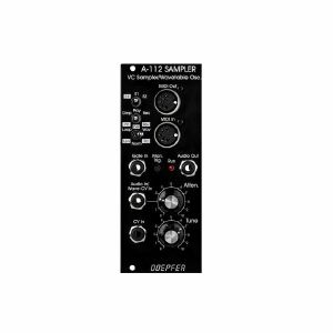
Otros clientes también compraron...
Doepfer A-112v Sampler VC Sampler & Wavetable Oscillator Vintage Edition Module (black) (delay/digital/oscillator/sampling synth module)
Cat: 671610 Rel: 29 Nov 17
Combined module of voltage-controlled 8-bit sampler & wavetable oscillator - vintage edition, 10HP
Notes: Module A-112 is the combination of a voltage controlled 8 Bit Sampler and a wavetable oscillator. On top of it the module is able to generate some special effects. A-112 was designed as an additional sound source with the typical sounds of the early 8 bit samplers and is not comparable with the modern polyphonic MIDI samplers available on the market.
Sampling mode: 8 bit audio resolution, 128kB memory in 2 banks 64kB each (equivalent to 2 seconds of sampling time for each bank with 32 kHz sampling rate), audio input with attenuator, overload display in record mode (gate LED), possibility of MIDI Dump to store sounds in a computer via MIDI, non-volatile memory for the 2 samples in the module, manual tune control for adjustment of sampling rate for record and play, CV input (~ 1V/Oct), both manual tune and CV determine the sampling rate respectively the pitch (pitch range is 5 octaves), gate input (not a trigger: the sample starts at the positive edge of the gate signal and is played as long as gate is high or until the end of the sample is reached), manual Gate button, non-filtered audio output (thus quantizing noise can be used as an element of the sound intentionally).
Wavetable mode: special appearance of the sampling mode when playing a sample, the audio input is now used as a second control voltage input for moving through the sample in 256 byte wide loops (wavetables). The control voltage required to move through all wavetables applied to the input "Wave CV In" is in the range -2.5V (wavetable 1) ... 0V (wavetable 127) ... +2.5V (wavetable 256) when control "Atten." is set fully clockwise. To achieve the typical wavetable oscillator sounds the sampling memory must contain corresponding wavetable data (e.g. loaded via MIDI dump). These data contain a set of wavetables with different harmonic content (e.g. a filter sweep) to get the typical wavetable sound while moving through the tables via CV. But you may also use a "normal" sample and go through the sample with CV to obtain partially amazing sounds never heard before. You may use for example sampled speech and go with CV through the syllables or speech shreds to get really very extreme sounds. An ideal addition for this feature is the Offset/Attenuator module A-183-2 which can be used to adjust the position of the wavetable (Offset) and the modulation depth (Att.). The corresponding jumper of the A-183-2 has to be set to bipolar offset (as the A-112 requires -2.5V...+2.5V to pass through all 256 wavetables). As modulation source an LFO (A-145, A-146, A-147, A-143-3), ADSR (A-140, A-141, A-142, A-143-1/2) or a random voltage (A-118, A-149-1) may be used. Even a ribbon controller (A-198 or R2M), the Theremin module A-178, the Joystick A-174 or the Wheels module A-174-2 are useful to drive through the wavetables.
Effects: Additionally, the module offers - in a way free of charge - some effects like delay, reverse delay, pitch shifting or freeze. But it has to be pointed out that due to the 8 bit audio resolution these effects are not comparable to high quality effect units and should be understand as an extra for nothing. The A-112 is not an effects unit!
The sampling time of the A-112 is about 1...30 seconds corresponding to a sampling frequency range of about 60kHz...2kHz (64kB@60kHz ~ 1 s, 64kB@2kHz ~ 30 s).
Technical note: the module uses a battery for the non-volatile storage of the sampling data. Batteries have a limited lifespan and have to be inspected at least every two years. For details please refer to the FAQ page of our website: Lifespan of rechargeable batteries (used for memory backup).
… Read moreSampling mode: 8 bit audio resolution, 128kB memory in 2 banks 64kB each (equivalent to 2 seconds of sampling time for each bank with 32 kHz sampling rate), audio input with attenuator, overload display in record mode (gate LED), possibility of MIDI Dump to store sounds in a computer via MIDI, non-volatile memory for the 2 samples in the module, manual tune control for adjustment of sampling rate for record and play, CV input (~ 1V/Oct), both manual tune and CV determine the sampling rate respectively the pitch (pitch range is 5 octaves), gate input (not a trigger: the sample starts at the positive edge of the gate signal and is played as long as gate is high or until the end of the sample is reached), manual Gate button, non-filtered audio output (thus quantizing noise can be used as an element of the sound intentionally).
Wavetable mode: special appearance of the sampling mode when playing a sample, the audio input is now used as a second control voltage input for moving through the sample in 256 byte wide loops (wavetables). The control voltage required to move through all wavetables applied to the input "Wave CV In" is in the range -2.5V (wavetable 1) ... 0V (wavetable 127) ... +2.5V (wavetable 256) when control "Atten." is set fully clockwise. To achieve the typical wavetable oscillator sounds the sampling memory must contain corresponding wavetable data (e.g. loaded via MIDI dump). These data contain a set of wavetables with different harmonic content (e.g. a filter sweep) to get the typical wavetable sound while moving through the tables via CV. But you may also use a "normal" sample and go through the sample with CV to obtain partially amazing sounds never heard before. You may use for example sampled speech and go with CV through the syllables or speech shreds to get really very extreme sounds. An ideal addition for this feature is the Offset/Attenuator module A-183-2 which can be used to adjust the position of the wavetable (Offset) and the modulation depth (Att.). The corresponding jumper of the A-183-2 has to be set to bipolar offset (as the A-112 requires -2.5V...+2.5V to pass through all 256 wavetables). As modulation source an LFO (A-145, A-146, A-147, A-143-3), ADSR (A-140, A-141, A-142, A-143-1/2) or a random voltage (A-118, A-149-1) may be used. Even a ribbon controller (A-198 or R2M), the Theremin module A-178, the Joystick A-174 or the Wheels module A-174-2 are useful to drive through the wavetables.
Effects: Additionally, the module offers - in a way free of charge - some effects like delay, reverse delay, pitch shifting or freeze. But it has to be pointed out that due to the 8 bit audio resolution these effects are not comparable to high quality effect units and should be understand as an extra for nothing. The A-112 is not an effects unit!
The sampling time of the A-112 is about 1...30 seconds corresponding to a sampling frequency range of about 60kHz...2kHz (64kB@60kHz ~ 1 s, 64kB@2kHz ~ 30 s).
Technical note: the module uses a battery for the non-volatile storage of the sampling data. Batteries have a limited lifespan and have to be inspected at least every two years. For details please refer to the FAQ page of our website: Lifespan of rechargeable batteries (used for memory backup).
out of stock $181.14
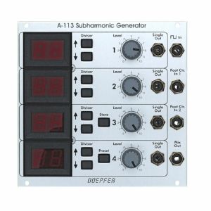
Otros clientes también compraron...
Doepfer A-113 Subharmonic Generator Module (silver) (waveshaper/frequency divider synth module)
Cat: 698542 Rel: 14 Aug 18
Sound source deriving four subharmonics from an incoming square wave signal - 26HP
Notes: Module A-113 is a new sound source that derives four so-called subharmonics (German: Subharmonische) from an incoming pulse signal. The term subharmonics was introduced by Oskar Sala in connection with his so-called Mixtur-Trautonium. A subharmonic means in this context a sawtooth wave (German: Kippschwinger) whose frequency is derived from a master frequency and the master frequency is an integer multiple in the range of 1...24 of the subharmonic - in other words: the master frequency is divided by an integer 1...24 to obtain the subharmonic.
The output waveform of a subharmonic is sawtooth (as also used in the original Trautonium) and not sine. The term subharmonics is somewhat misleading. The master frequency comes e.g. from an A-110 or A-111 to the frequency input of the A-113. The frequency dividers of the 4 subharmonics is adjusted with up/down buttons as displayed with two character LED displays. The subharmonics are available as single outputs and as mix output with adjustable levels for the subharmonics.
Two gate type control inputs enable to select between 4 different mixtures, i.e. 4 different settings of the frequency dividers. In the original Trautonium these are controlled by foot switches to switch between 3 mixtures while playing (the original Trautonium has only 3 mixtures available but with the 2 gate inputs of the A-113 four different settings can be addressed).
Additionally, the A-113 features a mixture memory with 50 presets. Each preset consists of 4 mixtures that can be selected with the gate inputs, each mixture contains the values of the 4 frequency dividers.
… Read moreThe output waveform of a subharmonic is sawtooth (as also used in the original Trautonium) and not sine. The term subharmonics is somewhat misleading. The master frequency comes e.g. from an A-110 or A-111 to the frequency input of the A-113. The frequency dividers of the 4 subharmonics is adjusted with up/down buttons as displayed with two character LED displays. The subharmonics are available as single outputs and as mix output with adjustable levels for the subharmonics.
Two gate type control inputs enable to select between 4 different mixtures, i.e. 4 different settings of the frequency dividers. In the original Trautonium these are controlled by foot switches to switch between 3 mixtures while playing (the original Trautonium has only 3 mixtures available but with the 2 gate inputs of the A-113 four different settings can be addressed).
Additionally, the A-113 features a mixture memory with 50 presets. Each preset consists of 4 mixtures that can be selected with the gate inputs, each mixture contains the values of the 4 frequency dividers.
out of stock $233.84

Otros clientes también compraron...
Doepfer A-114 Dual Ring Modulator Module (silver) (dual/stereo/ring modulator synth module)
Cat: 577797 Rel: 15 Aug 18
Two identical ring modulators in one module - 4HP
Notes: Module A-114 contains two separate ring modulators. A ring modulator outputs the product (Multiplication X - Y) of the signals at inputs X and Y. It's similar to a VCA, but whereas a VCA only responds to positive voltages at the inputs (2-quadrant multiplication), the ring modulator responds to both positive and negative voltages (4-quadrant multiplication).
The ring modulator thus provides a refinement of amplitude modulation (AM). Ordinary amplitude modulation will output the original carrier frequency fC as well as the two side bands (fC - fM, fC + fM) for each of the spectral components of the carrier and modulation signals - but ring modulation cancels out the carrier frequencies, and just lets the side-bands pass to the output (see Fig. 1).
A ring modulator is used for the production of bell-like sounds, alien voices, or just to produce new timbres.
… Read moreThe ring modulator thus provides a refinement of amplitude modulation (AM). Ordinary amplitude modulation will output the original carrier frequency fC as well as the two side bands (fC - fM, fC + fM) for each of the spectral components of the carrier and modulation signals - but ring modulation cancels out the carrier frequencies, and just lets the side-bands pass to the output (see Fig. 1).
A ring modulator is used for the production of bell-like sounds, alien voices, or just to produce new timbres.
out of stock $83.44
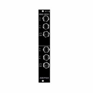
Otros clientes también compraron...
Doepfer A-114v Dual Ring Modulator Vintage Edition Module (black) (dual/stereo/ring modulator synth module)
Cat: 698544 Rel: 15 Aug 18
Two identical ring modulators in one module - 4HP
Notes: Module A-114 contains two separate ring modulators. A ring modulator outputs the product (Multiplication X - Y) of the signals at inputs X and Y. It's similar to a VCA, but whereas a VCA only responds to positive voltages at the inputs (2-quadrant multiplication), the ring modulator responds to both positive and negative voltages (4-quadrant multiplication).
The ring modulator thus provides a refinement of amplitude modulation (AM). Ordinary amplitude modulation will output the original carrier frequency fC as well as the two side bands (fC - fM, fC + fM) for each of the spectral components of the carrier and modulation signals - but ring modulation cancels out the carrier frequencies, and just lets the side-bands pass to the output (see Fig. 1).
A ring modulator is used for the production of bell-like sounds, alien voices, or just to produce new timbres.
… Read moreThe ring modulator thus provides a refinement of amplitude modulation (AM). Ordinary amplitude modulation will output the original carrier frequency fC as well as the two side bands (fC - fM, fC + fM) for each of the spectral components of the carrier and modulation signals - but ring modulation cancels out the carrier frequencies, and just lets the side-bands pass to the output (see Fig. 1).
A ring modulator is used for the production of bell-like sounds, alien voices, or just to produce new timbres.
out of stock $92.04
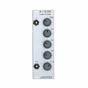
Otros clientes también compraron...
Doepfer A-115 Audio Divider Module (frequency divider synth module)
Cat: 698545 Rel: 15 Aug 18
Fourfold frequency divider for creating up to four sub-octaves - 8HP
Notes: Module A-115 is a four-way frequency divider. The frequency of a signal at the input is halved (half frequency = first sub-octave), quartered (1/4 frequency = second sub-octave), and so on. In this way, the DIVIDER produces four sub-octaves (F/2 down to F/16).
At the output, the A-115 produces a summed mix of the original and the four sub-octaves. There are attenuators to control the amount (i.e. Amplitude) of the original signal and each of the sub-octaves.
Bear in mind that the sub-octaves output by the A-115 are all true square waves. At the output there are always four square waves and the original signal available.
… Read moreAt the output, the A-115 produces a summed mix of the original and the four sub-octaves. There are attenuators to control the amount (i.e. Amplitude) of the original signal and each of the sub-octaves.
Bear in mind that the sub-octaves output by the A-115 are all true square waves. At the output there are always four square waves and the original signal available.
out of stock $63.67
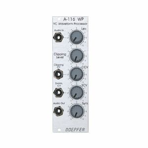
Otros clientes también compraron...
Doepfer A-116 Voltage Controlled Waveform Processor Module (processing synth module)
Cat: 698547 Rel: 15 Aug 18
Voltage controlled waveform processor module - 8HP
Notes: Module A-116 provides voltage-controlled dynamic waveform modification of audio signals. It can produce new waveforms from the standard VCO shapes, and modulate these changes in real time. The signal first of all goes through an input amplifier, which can attenuate the signal as well as amplify it by up to a factor of 2.
After the input amplifier, the signal goes through two parallel processors: a clipping circuit, and an asymmetrical amplifier. The processed signals are added together and sent to the output.
Clipping-Level and Symmetry amounts are not just manually controllable, but can also be modulated by control voltages, to produce complex, constantly changing waveforms.
… Read moreAfter the input amplifier, the signal goes through two parallel processors: a clipping circuit, and an asymmetrical amplifier. The processed signals are added together and sent to the output.
Clipping-Level and Symmetry amounts are not just manually controllable, but can also be modulated by control voltages, to produce complex, constantly changing waveforms.
out of stock $73.56
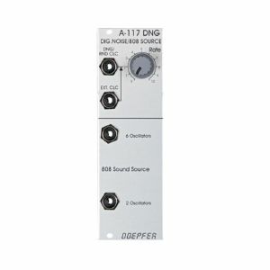
Otros clientes también compraron...
Cat: 698549 Rel: 15 Aug 18
Digital noise/random clock/808 sound source - 8HP
Notes: Module A-117 (DNG) is a combination module, including a digital noise generator and an 808 source.
The digital noise generator uses random sequences of square waves (18 step shift register with multiple feedback), whose rate can go from random clicks to noise. The colour of the noise is very different from the analogue noise produced by the A-118. The frequency range of the internal clock oscillator is about 100Hz - 100kHz.
In addition to a manual setting, the rate can be controlled by an external clock - eg. VCO, high speed VCO of A-188-1/2, LFO or MIDI clock.
The 808 Source aims to re-create the sort of multi-oscillator array that was used in Roland's TR-808 and 606 drum machines as the basis of the sound of the hi-hat, cymbals and cowbell. The cowbell mix uses two oscillators, and the cymbals mix six.
… Read moreThe digital noise generator uses random sequences of square waves (18 step shift register with multiple feedback), whose rate can go from random clicks to noise. The colour of the noise is very different from the analogue noise produced by the A-118. The frequency range of the internal clock oscillator is about 100Hz - 100kHz.
In addition to a manual setting, the rate can be controlled by an external clock - eg. VCO, high speed VCO of A-188-1/2, LFO or MIDI clock.
The 808 Source aims to re-create the sort of multi-oscillator array that was used in Roland's TR-808 and 606 drum machines as the basis of the sound of the hi-hat, cymbals and cowbell. The cowbell mix uses two oscillators, and the cymbals mix six.
out of stock $76.85
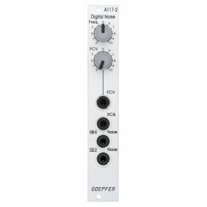
Otros clientes también compraron...
Doepfer A-117-2 Digital Noise Module (modular synthesiser)
Cat: 1021050 Rel: 05 Jul 24
Digital voltage controlled noise generator module - 4HP
Notes: Module A-117-2 contains a digital voltage controlled noise generator. It produces random sequences of square pulses whose rate can go from random clicks to audible noise. The colour of digital noise is different from analog noise. The frequency of the internal clock oscillator can adjusted manually (control "Frequ.") and via an external control voltage input ("FCV") with associated attenuator. The internal clock range is about 50Hz to 40kHz. With control FCV fully clockwise the sensitivity of the control voltage input is roughly 1V/octave.
Alternatively the noise rate can be controlled by an external clock signal (e.g. from a VCO, High-Speed-VCO, LFO, midi clock). For this the "XClk" socket is provided. As soon as a patch cable is inserted into this socket the internal oscillator is turned off and the signal applied to the XClk" socket is used to generate the noise instead of the internal clock signal.
The module has two noise outputs available: a zero-symmetrical output (upper noise socket) and pure positive output (lower noise socket). The symmetrical signal is used primarily for audio applications. The positive output is used primarily for digital control applications (e.g. random envelope triggering, random clock signal or random switching functions).
Width: 4TE / 4HP / 20.0 mm
Depth: 20 mm (measured from the rear side of the front panel)
Current: +?mA (+12V) / -?mA (-12V)
… Read moreAlternatively the noise rate can be controlled by an external clock signal (e.g. from a VCO, High-Speed-VCO, LFO, midi clock). For this the "XClk" socket is provided. As soon as a patch cable is inserted into this socket the internal oscillator is turned off and the signal applied to the XClk" socket is used to generate the noise instead of the internal clock signal.
The module has two noise outputs available: a zero-symmetrical output (upper noise socket) and pure positive output (lower noise socket). The symmetrical signal is used primarily for audio applications. The positive output is used primarily for digital control applications (e.g. random envelope triggering, random clock signal or random switching functions).
Width: 4TE / 4HP / 20.0 mm
Depth: 20 mm (measured from the rear side of the front panel)
Current: +?mA (+12V) / -?mA (-12V)
out of stock $91.12