
 USD
USDMi Idioma


Mi Divisa
Ayuda
Cómo hacer un pedidoProblemas al hacer un pedidoPreguntas más frecuentesContáctenosContact Us (Suppliers)Acerca de JunoJuno DailyEstrenos de esta semanaDJ & Studio StoreTagsComentariosPolítica de privacidadReturns & refundsCondiciones de usoFinanceJuno Vinyl DistributionJuno Vinyl WholesaleJuno Marketing and PR departmentPromote your label / releases


Filter
Stock

Format
Brand
Featured
Price
Tags
Back catalogue: All genres
Juno's full catalogue of All genres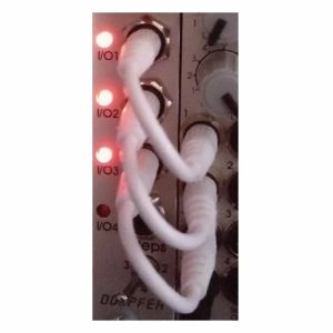
Otros clientes también compraron...
Doepfer A-100CXS 8.5cm Synth Module Patch Cable (single, white) (synth module patch cable)
Cat: 1066339 Rel: 04 Feb 25
Patch cable for ultra short connections in the modular synthesiser 8.5 cm, white mono jack plugs 3.5 mm at both ends
Notes: Patch cable for ultra short connections in the modular synthesiser 8.5 cm, white mono jack plugs 3.5 mm at both ends
… Read moreMore than 10 in stock $1.70
Otros clientes también compraron...
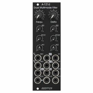
Doepfer A-121d Dual Multimode Filter Module (vintage edition) (modular synthesiser)
Cat: 1021083 Rel: 06 Sep 24
Dual multimode filter module - 8HP
Notes: Module A-121d is a special dual multimode filter which can be used for parallel or serial organized dual mono filters. Even stereo applications are imaginable. The filters are based on two special circuits: one with highpass and bandpass outputs, the other with lowpass and bandpass outputs. It's a new filter design that is not used so far in any other A-100 filter module.
We attached great importance to the usability of the manual controls and CV inputs for dual filter applications: for the filter frequencies of both filters a common control (Frequ.) and a difference control (Delta, filter spread) are available. For both parameters even CV inputs are available (FCV, DCV). The resonance (Q1, Q2), the sensitivity of the individual frequency control input (FCV1, FCV2) and the level of the audio input (In1, In2) are adjusted by means of the individual controls for each filter.
The module has a simple audio mixing unit available with the inputs Mx1 and Mx2, and the output MxO. Provided that the mixer inputs are open bandpass 1 and bandpass 2 are normalised to the sockets Mx1 and Mx2. All other filter types are realized by connecting the other filter outputs (H1 = highpass 1, L2 = lowpass 2) to the mixer inputs.
Controls:
Frequ.: master frequency control for both filters
Delta: controls the difference between the frequencies of the two filters manually (frequency spread), at centre position the frequencies are about the same
Q1 / Q2: resonance controls for filter 1 and 2
FCV1 / FCV2: attenuators for the individual frequency control inputs FCV1 (filter 1) and FCV2 (filter 2)
In 1 / In 2: attenuators for the audio inputs of filter 1 and 2
Sockets:
Mx1 / Mx2: audio inputs of the mixer, Mx1 is normalised to bandpass 1 (B1), Mx2 is normalised to bandpass 2 (B2)
MxO: audio output of the mixer
In1 / In2: audio input of filter 1 and 2 (In2 is normalised to In1)
H1: highpass output filter 1
L2: lowpass output filter 2
B2: bandpass output filter 2
DCV: control voltage input for frequency spread (Delta)
FCV1 / FCV2: individual frequency control inputs, processed by the attenuators FCV1 and FCV2, socket FCV2 is normalised to socket FCV1
FCV: common frequency control input for both filters (~ 1V/oct)
Triangle symbols indicate the normalising of sockets (B1>Mx1, B2>Mx2, In1>In2, FCV>FCV2). The four outputs are inverse labelled.
Technical note:
Ex factory the module is adjusted so that the resonance of the two filters does not reach self-oscillation. If desired the filters can be modified by the user by means of two trimming potentiometers so that self-oscillation is possible.
Dimensions
8 HP
41 mm deep
… Read moreWe attached great importance to the usability of the manual controls and CV inputs for dual filter applications: for the filter frequencies of both filters a common control (Frequ.) and a difference control (Delta, filter spread) are available. For both parameters even CV inputs are available (FCV, DCV). The resonance (Q1, Q2), the sensitivity of the individual frequency control input (FCV1, FCV2) and the level of the audio input (In1, In2) are adjusted by means of the individual controls for each filter.
The module has a simple audio mixing unit available with the inputs Mx1 and Mx2, and the output MxO. Provided that the mixer inputs are open bandpass 1 and bandpass 2 are normalised to the sockets Mx1 and Mx2. All other filter types are realized by connecting the other filter outputs (H1 = highpass 1, L2 = lowpass 2) to the mixer inputs.
Controls:
Frequ.: master frequency control for both filters
Delta: controls the difference between the frequencies of the two filters manually (frequency spread), at centre position the frequencies are about the same
Q1 / Q2: resonance controls for filter 1 and 2
FCV1 / FCV2: attenuators for the individual frequency control inputs FCV1 (filter 1) and FCV2 (filter 2)
In 1 / In 2: attenuators for the audio inputs of filter 1 and 2
Sockets:
Mx1 / Mx2: audio inputs of the mixer, Mx1 is normalised to bandpass 1 (B1), Mx2 is normalised to bandpass 2 (B2)
MxO: audio output of the mixer
In1 / In2: audio input of filter 1 and 2 (In2 is normalised to In1)
H1: highpass output filter 1
L2: lowpass output filter 2
B2: bandpass output filter 2
DCV: control voltage input for frequency spread (Delta)
FCV1 / FCV2: individual frequency control inputs, processed by the attenuators FCV1 and FCV2, socket FCV2 is normalised to socket FCV1
FCV: common frequency control input for both filters (~ 1V/oct)
Triangle symbols indicate the normalising of sockets (B1>Mx1, B2>Mx2, In1>In2, FCV>FCV2). The four outputs are inverse labelled.
Technical note:
Ex factory the module is adjusted so that the resonance of the two filters does not reach self-oscillation. If desired the filters can be modified by the user by means of two trimming potentiometers so that self-oscillation is possible.
Dimensions
8 HP
41 mm deep
1 in stock $169.51
Click for better price!
or call +44 20 7424 1960
quote 1021083
quote 1021083
Otros clientes también compraron...
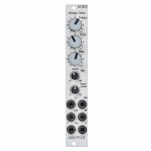
Doepfer A-124-2 Wasp Filter Module (silver, slim line) (filter synth module)
Cat: 1021093 Rel: 06 Sep 24
Wasp filter module - 4HP
Notes: Module A-124-2 is a special 12dB multimode filter using the "strange" filter circuit of the "EDP Wasp" (an analog synthesizer with black/yellow case built end of the seventies, manufactured by the UK company "Electronic Dream Plant").
The A-124-2 is the Slim Line version, which is only 4hp wide.
This design "abuses" digital inverters as analog operational amplifiers leading to distortions and other "dirty" effects that generate the specific sound of this filter. The filter is equipped with a band pass output and a combined low/notch/high pass output. For this output a control knob defines the relation between low and high pass signal. If both signals appear at the same level (i.e. middle position of the Mix knob) one obtains a notch filter. Otherwise the low or high pass signal predominates. The module does not feature self oscillation in contrast to most of the other filters of the A-100 system.
Dimensions:
4 HP
20 mm deep
… Read moreThe A-124-2 is the Slim Line version, which is only 4hp wide.
This design "abuses" digital inverters as analog operational amplifiers leading to distortions and other "dirty" effects that generate the specific sound of this filter. The filter is equipped with a band pass output and a combined low/notch/high pass output. For this output a control knob defines the relation between low and high pass signal. If both signals appear at the same level (i.e. middle position of the Mix knob) one obtains a notch filter. Otherwise the low or high pass signal predominates. The module does not feature self oscillation in contrast to most of the other filters of the A-100 system.
Dimensions:
4 HP
20 mm deep
1 in stock $125.43
Click for better price!
or call +44 20 7424 1960
quote 1021093
quote 1021093
Otros clientes también compraron...
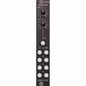
Doepfer A-130-4 Quad VCA Module (vintage edition) (modular synthesiser)
Cat: 1021146 Rel: 05 Jul 24
Quad voltage controlled amplifier module - 4HP
Notes: Module A-130-4 contains four linear VCAs with a common level control section for all four VCAs. It can be used for all applications of simultaneous amplitude/level control of up to four different audio or CV signals. A-130-4 is the replacement of the no longer available module A-132-2. Compared to the A-132-2 the width has been reduced from 8HP to 4HP.
The module has these controls and in/outputs available:
Control Man.: manual control of the amplification
Control CV: attenuator for the control voltage applied to socket CVo socket Input 1
Sockets In 1...4: VCA inputs 1...4
Sockets Out 1...4: VCA outputs 1...4
Application examples:
simultaneous amplitude/level control of up to four different audio or CV signals
polyphonic application 1: simultaneous control of the frequency modulation depth of 4 VCOs (Quad-LFO A-145-4 or Quad-VCLFO A-147-5 > A-130-4 > FM inputs A-111-4)
polyphonic application 2: simultaneous control of the pulsewidth modulation depth of 4 VCOs (Quad-LFO A-145-4 or Quad-VCLFO A-147-5 > A-130-4 > PWM inputs A-111-4)
simultaneous control of quadrophonic signals
Technical notes:
The maximum amplification for each VCA is about 1 ("Man." control fully CW). Even with an external control voltage applied to the CV input the maximum amplification is limited to 1.
The module is equipped with two internal connectors (pin headers with 4 pins each). Pin header #1 can be used to normalize the four inputs to other modules (e.g. Quad LFO A-145-4 or A-147-5, Quad ADSR A-143-2). Pin header #2 can be used to connect the four outputs to other modules.
The max. level at the VCA inputs without clipping/distortion is about 20Vpp or +/-10V.
Width: 4 HP / 20.0 mm
Depth: 45 mm (measured from the rear side of the front panel)
Current: +30 mA (+12V) / -30 mA (-12V)
… Read moreThe module has these controls and in/outputs available:
Control Man.: manual control of the amplification
Control CV: attenuator for the control voltage applied to socket CVo socket Input 1
Sockets In 1...4: VCA inputs 1...4
Sockets Out 1...4: VCA outputs 1...4
Application examples:
simultaneous amplitude/level control of up to four different audio or CV signals
polyphonic application 1: simultaneous control of the frequency modulation depth of 4 VCOs (Quad-LFO A-145-4 or Quad-VCLFO A-147-5 > A-130-4 > FM inputs A-111-4)
polyphonic application 2: simultaneous control of the pulsewidth modulation depth of 4 VCOs (Quad-LFO A-145-4 or Quad-VCLFO A-147-5 > A-130-4 > PWM inputs A-111-4)
simultaneous control of quadrophonic signals
Technical notes:
The maximum amplification for each VCA is about 1 ("Man." control fully CW). Even with an external control voltage applied to the CV input the maximum amplification is limited to 1.
The module is equipped with two internal connectors (pin headers with 4 pins each). Pin header #1 can be used to normalize the four inputs to other modules (e.g. Quad LFO A-145-4 or A-147-5, Quad ADSR A-143-2). Pin header #2 can be used to connect the four outputs to other modules.
The max. level at the VCA inputs without clipping/distortion is about 20Vpp or +/-10V.
Width: 4 HP / 20.0 mm
Depth: 45 mm (measured from the rear side of the front panel)
Current: +30 mA (+12V) / -30 mA (-12V)
1 in stock $106.23
Click for better price!
or call +44 20 7424 1960
quote 1021146
quote 1021146

Otros clientes también compraron...
Doepfer A-135-5v Polyphonic Voltage Controlled Mixer/Sub octave Generator Module (vintage edition) (modular synthesiser)
Cat: 1046643 Rel: 08 Nov 24
Polyphonic voltage controlled mixer/suboctave generator module - 10HP
Notes: Module A-135-5 is a combination of a voltage controlled polyphonic mixer and a polyphonic suboctave generator.
Module A-135-5 is a combination of a voltage controlled polyphonic mixer and a polyphonic suboctave generator. It is made of 12 voltage-controlled amplifiers (VCAs) which are arranged in form of a 4x3 matrix. Herewith up to three four-voice polyphonic signals (e.g. the outputs of three polyphonic VCOs A-111-4) can be mixed. The level of each of the three polyphonic channels (A, B, C) with four voices each can be controlled manually or by means of an external control voltage with associated attenuators.
In addition, the module features four frequency dividers which derive the suboctaves from the four input signals of channel A. The suboctave signals are wired to the switching contacts of the sockets of channel B. As long as the sockets of channel B are not patched the suboctave signals of channel A are used as inputs for channel B. The suboctaves are symmetrical rectangle waves with half the frequency of the corresponding signal A. For example, two polyphonic VCOs A-111-4) can be used and patched to the channels A and C. Channel B then provides the suboctaves of channel A.
The switching contacts of the 12 input sockets and the four outputs are internally connected to pin headers. That way the module can be internally pre-patched to other polyphonic modules (e.g. the four inputs A to an A-111-4, the four inputs C to another A-111-4 and the outputs to the polyphonic filter A-105-4). As the switching contacts of the sockets are used for the internal pre-patching the internal patch can be overridden by using the sockets at the front panel.
Technical notes:
If required two or more modules can be cascaded when more than three polyphonic channels are required.
The max. overall amplification is less than 1 to avoid clipping (can be altered to amplification 1 by replacing resistors, but then clipping may occur)
The max. input levels without distortion are about 16Vpp (or -8V ... +8V for the processing of control signals)
The voltage range for each of the CV inputs is about 0...+5V (with corresponding attenuator control fully CW), higher control voltages (e.g. 0...+10V) can be adjusted by means of the attenuator control
The suboctave levels are about 5Vpp
The module should be used only with DC coupled VCO outputs (e.g. A-111-4, A-111-3). With AC coupled VCO outputs (e.g. A-110-1, A-110-2) a DC offset will occur at the outputs when the suboctave option is installed.
The document A135_5_INTERNAL explains the positions and functions of the internal pin headers and describes the cascading of two A-135-5
… Read moreModule A-135-5 is a combination of a voltage controlled polyphonic mixer and a polyphonic suboctave generator. It is made of 12 voltage-controlled amplifiers (VCAs) which are arranged in form of a 4x3 matrix. Herewith up to three four-voice polyphonic signals (e.g. the outputs of three polyphonic VCOs A-111-4) can be mixed. The level of each of the three polyphonic channels (A, B, C) with four voices each can be controlled manually or by means of an external control voltage with associated attenuators.
In addition, the module features four frequency dividers which derive the suboctaves from the four input signals of channel A. The suboctave signals are wired to the switching contacts of the sockets of channel B. As long as the sockets of channel B are not patched the suboctave signals of channel A are used as inputs for channel B. The suboctaves are symmetrical rectangle waves with half the frequency of the corresponding signal A. For example, two polyphonic VCOs A-111-4) can be used and patched to the channels A and C. Channel B then provides the suboctaves of channel A.
The switching contacts of the 12 input sockets and the four outputs are internally connected to pin headers. That way the module can be internally pre-patched to other polyphonic modules (e.g. the four inputs A to an A-111-4, the four inputs C to another A-111-4 and the outputs to the polyphonic filter A-105-4). As the switching contacts of the sockets are used for the internal pre-patching the internal patch can be overridden by using the sockets at the front panel.
Technical notes:
If required two or more modules can be cascaded when more than three polyphonic channels are required.
The max. overall amplification is less than 1 to avoid clipping (can be altered to amplification 1 by replacing resistors, but then clipping may occur)
The max. input levels without distortion are about 16Vpp (or -8V ... +8V for the processing of control signals)
The voltage range for each of the CV inputs is about 0...+5V (with corresponding attenuator control fully CW), higher control voltages (e.g. 0...+10V) can be adjusted by means of the attenuator control
The suboctave levels are about 5Vpp
The module should be used only with DC coupled VCO outputs (e.g. A-111-4, A-111-3). With AC coupled VCO outputs (e.g. A-110-1, A-110-2) a DC offset will occur at the outputs when the suboctave option is installed.
The document A135_5_INTERNAL explains the positions and functions of the internal pin headers and describes the cascading of two A-135-5
1 in stock $222.36
Click for better price!
or call +44 20 7424 1960
quote 1046643
quote 1046643
Otros clientes también compraron...
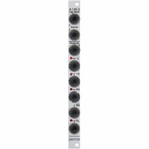
Doepfer A-165-2 Digital Modifiers Module (slim line) (modular synthesiser)
Cat: 1021149 Rel: 05 Jul 24
Digital modifiers module - 2HP
Notes: Module A-165-2 includes six modification circuits for digital signals (clock, gate, trigger, start, stop etc.) which are derived from the two input signals Input 1 und 2:
inverted signal of Input 1 (labelled 1)
inverted signal of Input 2 (labelled 2)
T flipflop (toggle flipflop), controlled by Input 1, this output changes it's state whenever a the rising edge of Input 1 appears (labelled 1/2, as it works similar to a 1:2 frequency divider)
Set/Reset flipflop, this output changes it's state to "high" during the rising edge of Input 1 and turns "low" during the rising edge of Input 2 (labelled RS)
inverted output of the Set/Reset flipflop (labelled RS)
pulse output, during both the rising and falling edge of Input 1 a short trigger pulse with about 50 ms lenght is generated (labelled with the sign ± and a rectangle pulse symbol)
The outputs 2, 1/2, RS and the pulse output are equipped with LEDs that display the state of the output in question.
The output level for all six outputs can be set to 0/+5V or 0/+11V by means of a jumper on the pc board.
Voltage thresholds for the input voltages:
voltages below +0,8 V are treated as "low"
voltages above +3 V are treated as "high"
Typical applications
starting and/or stopping of events or switching operations with the RS or RS output (e.g. controlled by the trigger outputs of a sequencer, e.g. in combination with electronic switches)
generation of inverted digital signals
frequency division (1/2 output)
generation of short pulses during the rising and falling edge of a digital signal (e.g. triggering an envelope at both rising and falling edge of a gate signal).
Technical notes
The module cannot be used for bipolar signals! The negative share of the input signal will be clipped by means of a so-called clipping diode at the input of module A-165-2. This may affect the output circuitry of the module connected to the A-165-2 (depends upon the details of the output circuit and if it is protected against clipping). For the planned field of application that's normally no limitation because these signals (clock, gate, trigger) work usually only with positive voltages.
The module can be used for analog signals only to a limited extend! With analog signals the inputs of the module work as comparators and the negative share of the input signal is clipped (as mentioned above).
Width: 2HP / 10.0 mm
Depth: ? mm (measured from the rear side of the front panel)
Current: +?mA (+12V) / -?mA (-12V)
… Read moreinverted signal of Input 1 (labelled 1)
inverted signal of Input 2 (labelled 2)
T flipflop (toggle flipflop), controlled by Input 1, this output changes it's state whenever a the rising edge of Input 1 appears (labelled 1/2, as it works similar to a 1:2 frequency divider)
Set/Reset flipflop, this output changes it's state to "high" during the rising edge of Input 1 and turns "low" during the rising edge of Input 2 (labelled RS)
inverted output of the Set/Reset flipflop (labelled RS)
pulse output, during both the rising and falling edge of Input 1 a short trigger pulse with about 50 ms lenght is generated (labelled with the sign ± and a rectangle pulse symbol)
The outputs 2, 1/2, RS and the pulse output are equipped with LEDs that display the state of the output in question.
The output level for all six outputs can be set to 0/+5V or 0/+11V by means of a jumper on the pc board.
Voltage thresholds for the input voltages:
voltages below +0,8 V are treated as "low"
voltages above +3 V are treated as "high"
Typical applications
starting and/or stopping of events or switching operations with the RS or RS output (e.g. controlled by the trigger outputs of a sequencer, e.g. in combination with electronic switches)
generation of inverted digital signals
frequency division (1/2 output)
generation of short pulses during the rising and falling edge of a digital signal (e.g. triggering an envelope at both rising and falling edge of a gate signal).
Technical notes
The module cannot be used for bipolar signals! The negative share of the input signal will be clipped by means of a so-called clipping diode at the input of module A-165-2. This may affect the output circuitry of the module connected to the A-165-2 (depends upon the details of the output circuit and if it is protected against clipping). For the planned field of application that's normally no limitation because these signals (clock, gate, trigger) work usually only with positive voltages.
The module can be used for analog signals only to a limited extend! With analog signals the inputs of the module work as comparators and the negative share of the input signal is clipped (as mentioned above).
Width: 2HP / 10.0 mm
Depth: ? mm (measured from the rear side of the front panel)
Current: +?mA (+12V) / -?mA (-12V)
1 in stock $96.06
Click for better price!
or call +44 20 7424 1960
quote 1021149
quote 1021149
Otros clientes también compraron...
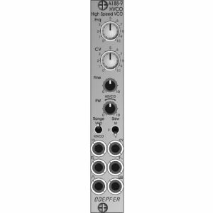
Doepfer A-188-9 HVCO High-Speed VCO Module (oscillator synth module)
Cat: 1046640 Rel: 12 Feb 25
High-speed voltage controlled oscillator module - 4HP
Notes: Module A-188-9 is a so-called high speed VCO that tracks perfectly to the 1V/oct scale in the frequency range of about 15kHz ... 500 kHz. The main application is the exact drive of BBD modules (A-188-1/2) to generate sounds realized by means of the so-called Karplus-Strong synthesis. But even in cooperation with other modules featuring high speed inputs (e.g. digital noise, delay, frequency divider) the A-188-9 makes sense. In principle the module is made of a precision audio VCO followed by a PLL (phase locked loop) unit that multiplies the frequency of the audio VCO by 32. Thus the module can be used also as an audio VCO as it features the standard waveforms sawtooth, triangle and rectangle with adjustable pulse width.
Controls:
Frq: frequency control (coarse)
CV: attenuator for the frequency control input CV
Fine: frequency control (fine), small control without knob
PW: pulsewidth control for the rectangle output of the audio VCO, in HSVCO mode this control has to be in the range marked "HSVO", small control without knob
Sockets:
1V: frequency control input 1V/oct scale
CV: frequency control input with attenuator CV
socket with rectangle symbol: rectangle output of the audio VCO, the pulse width of this output is adjusted by means of the control PW, output level ~ 7Vpp (~ -3.5V/+3.5V)
socket with sawtooth symbol: sawtooth output of the audio VCO, output level ~ 7Vpp (~ -3.5V ... +3.5V)
socket with triangle symbol: triangle output of the audio VCO, output level ~ 7Vpp (~ -3.5V ... +3.5V)
socket with inverted comb symbol: high speed VCO output, waveform rectangle, output level ~ 5Vpp (~ -2.5V/+2.5V)
Switches:
Range
upper position: audio VCO mode (frequency range of the audio VCO about 15 Hz to 6 kHz, the high speed output is not usable in this mode! )
lower position: High Speed VCO mode (frequency range of the high-speed output about 15 kHz ... 500 kHz, frequency range of the audio VCO about 500 Hz ... 15 kHz), in this mode the audio VCO and the high speed VCO can be used simultaneously
Slew
upper position: medium slew time
centre position: short slew time
lower position: long slew time
Technical Note regarding the Slew parameter:
Besides the audio VCO the module contains a so-called PLL circuit (Phase Locked Loop) and a 1:32 frequency divider. A slew limiter is part of the PLL. It defines how fast the frequency of the PLL follows the frequency of the VCO. The PLL cannot follow the VCO without any delay. Rather one has to find a compromise between the residual ripple of the PLL frequency and the frequency follow rate. That is the job of the slew limiter (works in principle like a glide or portamento unit). For this the module is equipped with a 3-position switch that is used to switch the slew time in 3 ranges. When mostly higher frequencies are used ((~ 100kHz ... 500 kHz) a short slew time can be chosen. When also lower frequencies are required (< 100kHz) a longer slew time may be used to reduce the residual frequency ripple. More details about the working principle of a PLL can be found in the information about module A-196. Module A-188-9 is in principle an A-196 combined with an audio VCO and a 1:32 frequency divider.
Width: 4HP / 20.0 mm
Depth: 45 mm (measured from the rear side of the front panel)
Current: +30 mA (+12V) / -15 mA (-12V)
… Read moreControls:
Frq: frequency control (coarse)
CV: attenuator for the frequency control input CV
Fine: frequency control (fine), small control without knob
PW: pulsewidth control for the rectangle output of the audio VCO, in HSVCO mode this control has to be in the range marked "HSVO", small control without knob
Sockets:
1V: frequency control input 1V/oct scale
CV: frequency control input with attenuator CV
socket with rectangle symbol: rectangle output of the audio VCO, the pulse width of this output is adjusted by means of the control PW, output level ~ 7Vpp (~ -3.5V/+3.5V)
socket with sawtooth symbol: sawtooth output of the audio VCO, output level ~ 7Vpp (~ -3.5V ... +3.5V)
socket with triangle symbol: triangle output of the audio VCO, output level ~ 7Vpp (~ -3.5V ... +3.5V)
socket with inverted comb symbol: high speed VCO output, waveform rectangle, output level ~ 5Vpp (~ -2.5V/+2.5V)
Switches:
Range
upper position: audio VCO mode (frequency range of the audio VCO about 15 Hz to 6 kHz, the high speed output is not usable in this mode! )
lower position: High Speed VCO mode (frequency range of the high-speed output about 15 kHz ... 500 kHz, frequency range of the audio VCO about 500 Hz ... 15 kHz), in this mode the audio VCO and the high speed VCO can be used simultaneously
Slew
upper position: medium slew time
centre position: short slew time
lower position: long slew time
Technical Note regarding the Slew parameter:
Besides the audio VCO the module contains a so-called PLL circuit (Phase Locked Loop) and a 1:32 frequency divider. A slew limiter is part of the PLL. It defines how fast the frequency of the PLL follows the frequency of the VCO. The PLL cannot follow the VCO without any delay. Rather one has to find a compromise between the residual ripple of the PLL frequency and the frequency follow rate. That is the job of the slew limiter (works in principle like a glide or portamento unit). For this the module is equipped with a 3-position switch that is used to switch the slew time in 3 ranges. When mostly higher frequencies are used ((~ 100kHz ... 500 kHz) a short slew time can be chosen. When also lower frequencies are required (< 100kHz) a longer slew time may be used to reduce the residual frequency ripple. More details about the working principle of a PLL can be found in the information about module A-196. Module A-188-9 is in principle an A-196 combined with an audio VCO and a 1:32 frequency divider.
Width: 4HP / 20.0 mm
Depth: 45 mm (measured from the rear side of the front panel)
Current: +30 mA (+12V) / -15 mA (-12V)
2 in stock $144.65
Click for better price!
or call +44 20 7424 1960
quote 1046640
quote 1046640

Otros clientes también compraron...
Doepfer A-192-2 Dual CV & Gate To MIDI & USB Interface Module (B-STOCK) (CV to MIDI synth module)
Cat: 1089637 Rel: 01 Jan 90
B-STOCK: Slight surface marks
Notes: ***B-STOCK: Slight surface marks ***
Module A-192-2 contains two independent CV/Gate-to-Midi/USB interfaces. For each of the two sub-units these inputs are available:
- Gate Input (min. +5V)
- CVN Input (defines the Midi note number), 1V/octave standard, range 0...+10V (i.e. 10 octaves)
- CVV Input (defines the velocity value assigned to the Midi note message), can be used alternatively for Midi volume (CC#7), range 0...+5V
- CVC Input (free assignable to any Midi control change number), range 0...+5V
For both sub-units a common CV Transpose input is available (1V/octave, range 0...+10V). The voltage applied to this input is added internally to CVN before the Midi note number is generated. It can be used e.g. to transpose two sequences simultaneously by one voltage.
How it works:
Whenever the rising edge of the Gate input is recognized a Midi note on message is generated. The note number corresponds to the sum of the voltages applied to the CVN input and the common CV Transpose Input that is present at the rising edge of the gate signal.
… Read moreModule A-192-2 contains two independent CV/Gate-to-Midi/USB interfaces. For each of the two sub-units these inputs are available:
- Gate Input (min. +5V)
- CVN Input (defines the Midi note number), 1V/octave standard, range 0...+10V (i.e. 10 octaves)
- CVV Input (defines the velocity value assigned to the Midi note message), can be used alternatively for Midi volume (CC#7), range 0...+5V
- CVC Input (free assignable to any Midi control change number), range 0...+5V
For both sub-units a common CV Transpose input is available (1V/octave, range 0...+10V). The voltage applied to this input is added internally to CVN before the Midi note number is generated. It can be used e.g. to transpose two sequences simultaneously by one voltage.
How it works:
Whenever the rising edge of the Gate input is recognized a Midi note on message is generated. The note number corresponds to the sum of the voltages applied to the CVN input and the common CV Transpose Input that is present at the rising edge of the gate signal.
1 in stock $132.22