
 USD
USDMi Idioma


Mi Divisa
Ayuda
Cómo hacer un pedidoProblemas al hacer un pedidoPreguntas más frecuentesContáctenosContact Us (Suppliers)Acerca de JunoJuno DailyEstrenos de esta semanaDJ & Studio StoreTagsComentariosPolítica de privacidadReturns & refundsCondiciones de usoFinanceJuno Vinyl DistributionJuno Vinyl WholesaleJuno Marketing and PR departmentPromote your label / releases


Filter

Equipment
Format
Brand
Featured
Price
Tags
All genres charts
Bestselling All genres vinyl
Artículos del 1 al 6 de 6 en la página 1 de 1
Otros clientes también compraron...
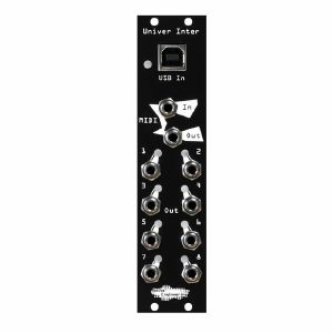
Noise Engineering Univer Inter Chainable 8-Output MIDI To CV Converter & USB MIDI Interface Module (black) (MIDI synth module)
Cat: 955808 Rel: 10 Jul 23
Chainable 8-output MIDI to CV converter and USB MIDI interface module - 6HP.
Notes: Describing Univer Inter as merely a MIDI-to-CV module falls short of its immense potential. It serves as an all-encompassing MIDI-to-any-format converter, elegantly packed into a compact 6 HP unit. Connect to your gear via USB B or TRS MIDI, or use the included adapter to plug straight into those 5-pin DIN connecters we all know and love. Whether you're looking to map clock, note, CC, aftertouch or something else that MIDI can encode, UI can do it: we built in over 20 settings for each of the 8 outputs.
Want to control a pair of monophonic voices, complete with velocity and aftertouch? No problem. How about a polyphonic setup, with gate and pitch per voice? Easy. Need to synchronize an in-the-rack sequencer with your DAW or a MIDI clock? UI has you covered.
Eight outputs isn't enough, you say? Chain two UI together via their front-panel MIDI ports and a TRS cable for 16 - you read that right, 16 - configurable CV outputs from a single MIDI connection. The possibilities are endless.
Noise Engineering also made configuration simple via the front-panel USB connection and the easy-to-use Univer Inter section on the Noise Engineering Customer Portal. Go wild and set each channel to any output option you need, or just use one of our simple presets. Configuration files can also be saved as sysex files for easy backup and sharing.
Features
Size and Power
6HP Eurorack
+12v: 40mA
-12v: 10mA
Univer - from Latin: "Universe"
Inter - from Latin: "between"
"Between universes"
What's in the box:
Module
Power cable
5-pin MIDI to TRS cable
USB A to B cable
To reduce excess materials, screws will no longer be included with Noise Engineering modules beginning in 2023.
… Read moreWant to control a pair of monophonic voices, complete with velocity and aftertouch? No problem. How about a polyphonic setup, with gate and pitch per voice? Easy. Need to synchronize an in-the-rack sequencer with your DAW or a MIDI clock? UI has you covered.
Eight outputs isn't enough, you say? Chain two UI together via their front-panel MIDI ports and a TRS cable for 16 - you read that right, 16 - configurable CV outputs from a single MIDI connection. The possibilities are endless.
Noise Engineering also made configuration simple via the front-panel USB connection and the easy-to-use Univer Inter section on the Noise Engineering Customer Portal. Go wild and set each channel to any output option you need, or just use one of our simple presets. Configuration files can also be saved as sysex files for easy backup and sharing.
Features
Size and Power
6HP Eurorack
+12v: 40mA
-12v: 10mA
Univer - from Latin: "Universe"
Inter - from Latin: "between"
"Between universes"
What's in the box:
Module
Power cable
5-pin MIDI to TRS cable
USB A to B cable
To reduce excess materials, screws will no longer be included with Noise Engineering modules beginning in 2023.
1 in stock $285.44
Click for better price!
or call +44 20 7424 1960
quote 955808
quote 955808
Otros clientes también compraron...
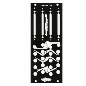
Noise Engineering Lapsus Os 4-Channel Attenuverter/Attenuator Module (black) (attenuator synth module)
Cat: 836849 Rel: 18 Aug 21
Quad-channel attenuverter/attenuator and offset with faders
Notes: Performance-focussed four-channel attenuverter and offset module, with built-in voltage generator for 0-5v or i5v voltages. Simple but effective.
Supplier's Notes:
Lapsus Os is a four channel attenuator/attenuverter and offset. Designed with performance in mind, each channel can be set to either attenuate or attenuate/invert an incoming signal, adjust offset of an incoming signal, or with nothing patched to its input, generate a 0-5v or i5v offset. Switches on the back of the module invert the fader behavior, allowing for the module to be mounted in either direction, for further customization and ease of use.
Etymology
Lapsus -- from latin lapsus : 'sliding' Os -- from latin os 'bones'
"Translation: Dancing Corpse"
Interface
Faders 1-4: The main controls of LO. The LEDs in the faders show the CV that is being passed through. When in attenuverter mode, the LED will be off at 0, allowing each fader to easily be set near 0.
Offset inputs 1-4 (+): Sending a signal to these inputs adds an offset to the input, controlled by the fader and the mode switch.
Outputs: Each channel has a pair of identical outputs. If nothing is sent to either input of a channel, an offset will be generated and output here, useful for controlling parameters on other modules with a single fader.
Uni/Bi Switches 1-4: In the Unipolar position (left), the corresponding channel attenuates the input signal. In the Bipolar position (right), the upper half of the corresponding channel fader attenuates the input signal, the lower half of the fader inverts and attenuates the signal.
Attenuating/attenuverting inputs 1-4 (x): Sending a signal to these inputs attenuates/attenuverts the signal, depending on the position of the channel fader and switch.
Rear-board switches: Below, in red. Inverts the corresponding channel, allowing for creative mounting in either direction. Note that each channel must be switched independently to fully reverse the functionality.
Patch Tutorial
Patch 1: Set a channel switch to the left position and patch the outputs to CV inputs on another module (for instance, Loquelic Iteritas). The fader becomes an easy-to-use controller for those parameters. Patch the rest of the LO channels to other parameters in your system to create an expressive and intuitive interface.
Patch 2: Patch a CV signal (such as an LFO) into the attenuverting input of a channel. Set the channel switch to the right position, and patch the output to a bipolar CV input in your system. Tweak the fader to attenuvert and dial in the perfect amount of modulation on the fly.
Patch 3: In a case with four voices route each LO channel to the decay control for each voice. Use for centralized control over voicing.
Size: 10HP Eurorack
Depth .8 Inches
Power 2x5 Eurorack
+12 mA 60 mA
-12 mA 50 mA
Inputs: i10v
Outputs (without voltage applied):
Unipolar: 0-5v
Bipolar: i5v
… Read moreSupplier's Notes:
Lapsus Os is a four channel attenuator/attenuverter and offset. Designed with performance in mind, each channel can be set to either attenuate or attenuate/invert an incoming signal, adjust offset of an incoming signal, or with nothing patched to its input, generate a 0-5v or i5v offset. Switches on the back of the module invert the fader behavior, allowing for the module to be mounted in either direction, for further customization and ease of use.
Etymology
Lapsus -- from latin lapsus : 'sliding' Os -- from latin os 'bones'
"Translation: Dancing Corpse"
Interface
Faders 1-4: The main controls of LO. The LEDs in the faders show the CV that is being passed through. When in attenuverter mode, the LED will be off at 0, allowing each fader to easily be set near 0.
Offset inputs 1-4 (+): Sending a signal to these inputs adds an offset to the input, controlled by the fader and the mode switch.
Outputs: Each channel has a pair of identical outputs. If nothing is sent to either input of a channel, an offset will be generated and output here, useful for controlling parameters on other modules with a single fader.
Uni/Bi Switches 1-4: In the Unipolar position (left), the corresponding channel attenuates the input signal. In the Bipolar position (right), the upper half of the corresponding channel fader attenuates the input signal, the lower half of the fader inverts and attenuates the signal.
Attenuating/attenuverting inputs 1-4 (x): Sending a signal to these inputs attenuates/attenuverts the signal, depending on the position of the channel fader and switch.
Rear-board switches: Below, in red. Inverts the corresponding channel, allowing for creative mounting in either direction. Note that each channel must be switched independently to fully reverse the functionality.
Patch Tutorial
Patch 1: Set a channel switch to the left position and patch the outputs to CV inputs on another module (for instance, Loquelic Iteritas). The fader becomes an easy-to-use controller for those parameters. Patch the rest of the LO channels to other parameters in your system to create an expressive and intuitive interface.
Patch 2: Patch a CV signal (such as an LFO) into the attenuverting input of a channel. Set the channel switch to the right position, and patch the output to a bipolar CV input in your system. Tweak the fader to attenuvert and dial in the perfect amount of modulation on the fly.
Patch 3: In a case with four voices route each LO channel to the decay control for each voice. Use for centralized control over voicing.
Size: 10HP Eurorack
Depth .8 Inches
Power 2x5 Eurorack
+12 mA 60 mA
-12 mA 50 mA
Inputs: i10v
Outputs (without voltage applied):
Unipolar: 0-5v
Bipolar: i5v
1 in stock $226.81
Otros clientes también compraron...
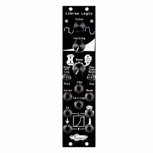
Noise Engineering Librae Legio Multi-Faceted Dynamics Processor Module (black) (digital/distortion/dual/stereo/dnamics/effect synth module)
Cat: 882642 Rel: 08 Jul 22
Compressor, expander, limiter, saturator, and more: put Librae at the end of your chain and listen to the magic
Notes: Librae Legio is a dynamics processor designed to take a whole patch to the next level. Compression, expansion, limiting, noise gating, and two styles of gentle distortion: Librae is the perfect tool to bring your mix together. And while it can do extreme limiting and really squash your sounds together, Noise Engineering developed it with transparency in mind - whether you want to hard-limit your techno mix or gently bring the sounds in your ambient patch together, Librae is the end-of-chain dynamics processor you've been looking for.
… Read more1 in stock $276.60
Otros clientes también compraron...
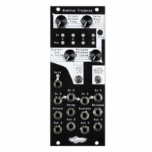
Noise Engineering Quantus Trajecta 4-Channel Polyphonic-Inspired Envelope Generator Module (black) (quad/envelope generator synth module)
Cat: 922507 Rel: 30 Jan 23
4-channel polyphonic-inspired envelope generator module with ADSR, tremelo and Percido-style envelopes - 10HP.
Notes: Quantus Trajecta is a quad envelope designed with polyphony in mind. Quantus Trajecta's envelope structure takes the functionality from Noise Engineering's beloved Loquelic and Cursus Iteritas Percido modules, and adds even more control and mode options like Tremolo and ADSR.
Each parameter is CV controllable, and each control universally adjusts all four envelopes for easy polyphonic tracking. Quantus Trajecta is performable, musical, and most importantly, fun.
… Read moreEach parameter is CV controllable, and each control universally adjusts all four envelopes for easy polyphonic tracking. Quantus Trajecta is performable, musical, and most importantly, fun.
1 in stock $219.06
Click for better price!
or call +44 20 7424 1960
quote 922507
quote 922507
Otros clientes también compraron...
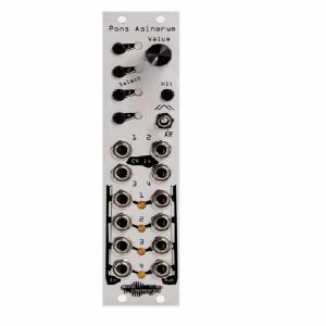
Noise Engineering Pons Asinorum 4-Channel Voltage-Controlled Linear Envelope Generator & LFO Module (silver) (envelope generator/LFO synth module)
Cat: 711981 Rel: 13 Dec 18
The bridge of asses. Quad CVable envelope/LFO with three envelope shapes.
Notes: Pons Asinorum is a compact four-channel multimode envelope generator and LFO with voltage control. PA has three different envelope shapes, CV over cycle length, and a unique single encoder control scheme that makes adjusting multiple channels mid-performance easy. Channels can be set separately to envelope mode or to cycle in LFO mode, giving PA maximal flexibility in a minimal footprint.
… Read more1 in stock $204.13
Click for better price!
or call +44 20 7424 1960
quote 711981
quote 711981
Otros clientes también compraron...
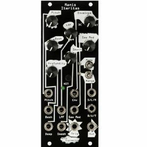
Noise Engineering Manis Iteritas Gross Industrial VCO Module (black) (B-STOCK) (digital/oscillator synth module)
Cat: 1065102 Rel: 01 Jan 90
B-STOCK: Item refurbished, repaired and in perfect working order.
Notes: ***B-STOCK: Item refurbished, repaired and in perfect working order.***
Manis Iteritas is a Eurorack 10HP voice based on the architecture of Basimilus Iteritas, but designed to be more gritty and aggressive. It accomplishes this by producing only sawtooth waves that are manipulated, modulated, and distorted through a rethought interface. Manis is suitable for leads, bass lines, drums, darkness, detuned madness, or pure mayhem.
… Read moreManis Iteritas is a Eurorack 10HP voice based on the architecture of Basimilus Iteritas, but designed to be more gritty and aggressive. It accomplishes this by producing only sawtooth waves that are manipulated, modulated, and distorted through a rethought interface. Manis is suitable for leads, bass lines, drums, darkness, detuned madness, or pure mayhem.
1 in stock $298.73
Artículos del 1 al 6 de 6 en la página 1 de 1